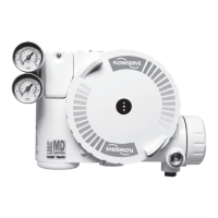
User Instructions - Logix® 520MD+ Series Digital Positioner
FCD LGENIM0105-00
© Flowserve Corporation 30 Field Trial Version – Printed October 28, 2011
used to tightly close or open the valve. It is used when a
tight seal is needed or when debris or friction may
otherwise interfere with complete closure. When the valve
is commanded past the Shutoff points, the pilot relay will
direct full supply pressure to the appropriate port, applying
all available force to close (or open) the valve. The Shutoff
points apply to the Final Command.
CAUTION: Changing the Shutoff limits may cause the
valve to fully open or fully close after the command passes
a set limit.
Though Shutoff and Soft Limit features should not be used
together, if both are set, the greater of the two settings will
take precedence at the closed end; and the lesser of the
two settings will take precedence at the open end.
10.3.9 Configuration (Set Time and Date)
The positioner has an internal clock. The clock allows time
and date information to be stored with alarms and other
events. The clock does not account for daylight savings.
Set Time and Date – Use the ▲Up and ▼Down buttons to
set the time and date. The format of the time and date is
displayed above the input fields.
10.3.10 Configuration (User Preferences)
The User Preferences menu allows the user to format how
information is displayed.
The following table shows the available options. By default
the positioner is set to show information in International
System (SI) units. To change all units to North American
(English), make the selection under All Units. Each
selection can also be changed individually.
Table 17: User Preference Options
Units/Format
International
System (SI)
(Default)
North
American
(English)
Other
Options
All Units SI North American -
Pressure bar PSI
kg/cm2,
kPa
Force N lbf kg
Temperature degrees C degrees F -
Air Flow slph scfm
slpm,
Nm3/hr
Actuator Area
cm
2
in
2
-
Date Format Day.Mon.Year Mon/Day/Year -
Number Comma Decimal Point -
LCD Orientation – Use this selection to turn the turn the
display upside down (180 degrees). Use this feature when
the positioner is mounted upside down.
10.3.11 Configuration (Burst Mode)
Burst Mode continuously transmits HART information.
On/Off – Use this feature to turn burst mode on and off.
10.3.12 Configuration (Positioner Revs)
Positioner revisions are shown in this menu.
SW Rev –The revision of the embedded software.
Bld Date –The date of the embedded software build.
Bld Time –The time of day of the embedded software build.
HW Rev –The revision of the main board.
CPU Rev – The revision of the CPU.
HART Ver –The revision of the HART protocol (5, 6, or 7).
10.3.13 Configuration (Factory Reset)
At times, it may be convenient to reset all of the variables
to a default state. In this case, perform a Factory Reset.
Factory Reset – Use this feature to reset all variables to
their factory default state. All of the internal variables
including calibration will be reset to factory defaults. The
positioner must be re-calibrated after a factory reset. Tag
names and other user configured limits, alarm settings, and
valve information will also be lost and will need to be
restored. A factory reset will always reset the command
source to analog 4-20 mA.
NOTE: Once the Multi-Function Card (MFC) type has
been configured, the type selection will still remain after a
factory reset.
WARNING: Performing a factory reset may result in the
inability to operate the valve until reconfigured properly.
Notify proper personnel that the valve may stroke, and
make sure the valve is properly isolated.
10.3.14 Card 1 (or Card 2)
Two slots are available for auxiliary cards. The Multi-
Function Card (MFC) can be configured for analog output
(AO), Discrete Input (DI) and Discrete Output (DO). The
Safety Discrete Output card (Safety DO) provides highly
 Loading...
