17
®
User Instructions Logix 520MD - LGENIM0520-01 11/09
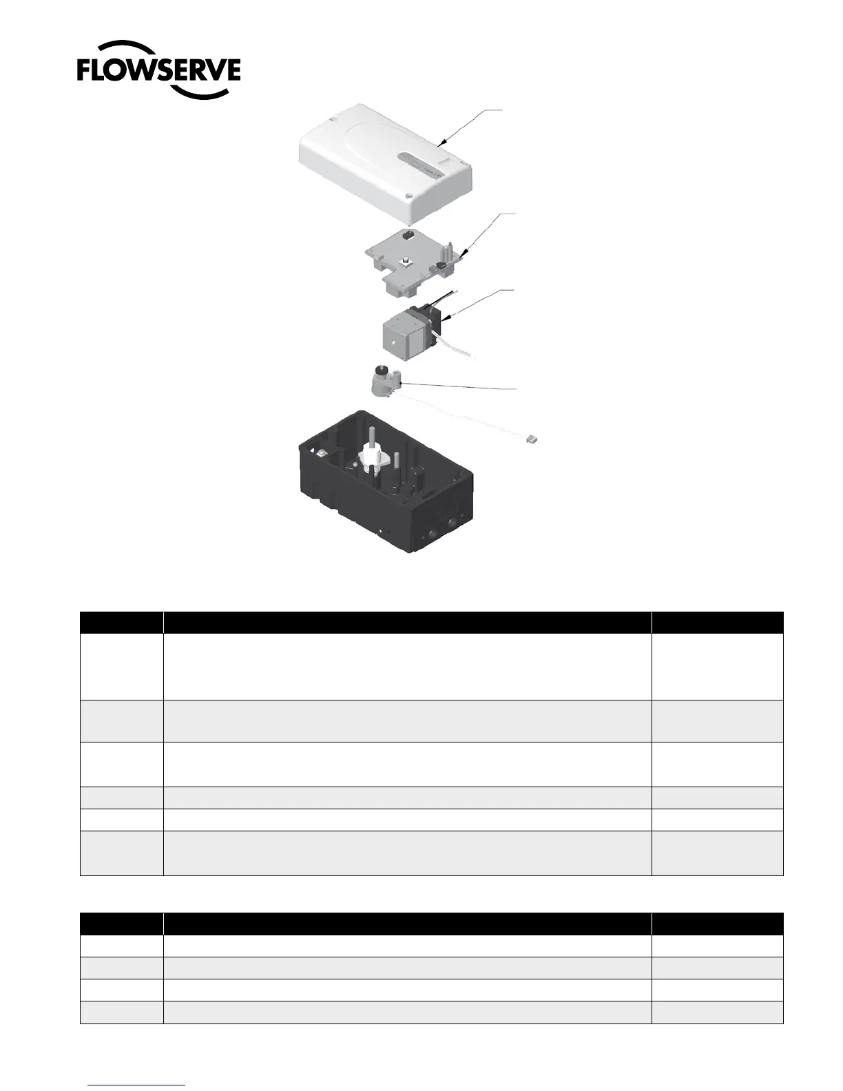
15 SPARE PARTS KITS
Item No. Description Part-No.
1 Cover Assembly Yellow 255240.999.000
White 218771.999.000
Black 218772.999.000
2
PC Board Assembly Logix 520MD
PC Board Assembly analog feedback board
255349.999.000
255463.999.000
3
Relay Module Assembly: -20ºC to 85ºC (-4ºF to 185ºF) 230103.999.000
Relay Module Assembly: -40ºC to 85ºC (-40ºF to 185ºF) 218773.999.000
4 Repair kit for Potentiometer Assembly 218774.999.000
5 Position Feedback Assembly 218774.999.000
8 Follower Arm Assembly Max. stroke 65 mm 214323.999.000
Max. stroke 110 mm 214322.999.000
Mounting Kits
Description Part-No.
– IEC 534 part 6 (FloTop, Kämmer KA, Kämmer KP, and standard NAMUR linear valves) 213619.999.000
– Rotary VDI/VDE 3845 (DIN ISO 5211) 188151.999.000
– Flowserve direct mounting 214004.999.000
– Linear VDI / VDE 3847 255242.999.000
Figure 9: Exploded drawing for spare parts
1
2
3
4

 Loading...


