13
+
–
+
–
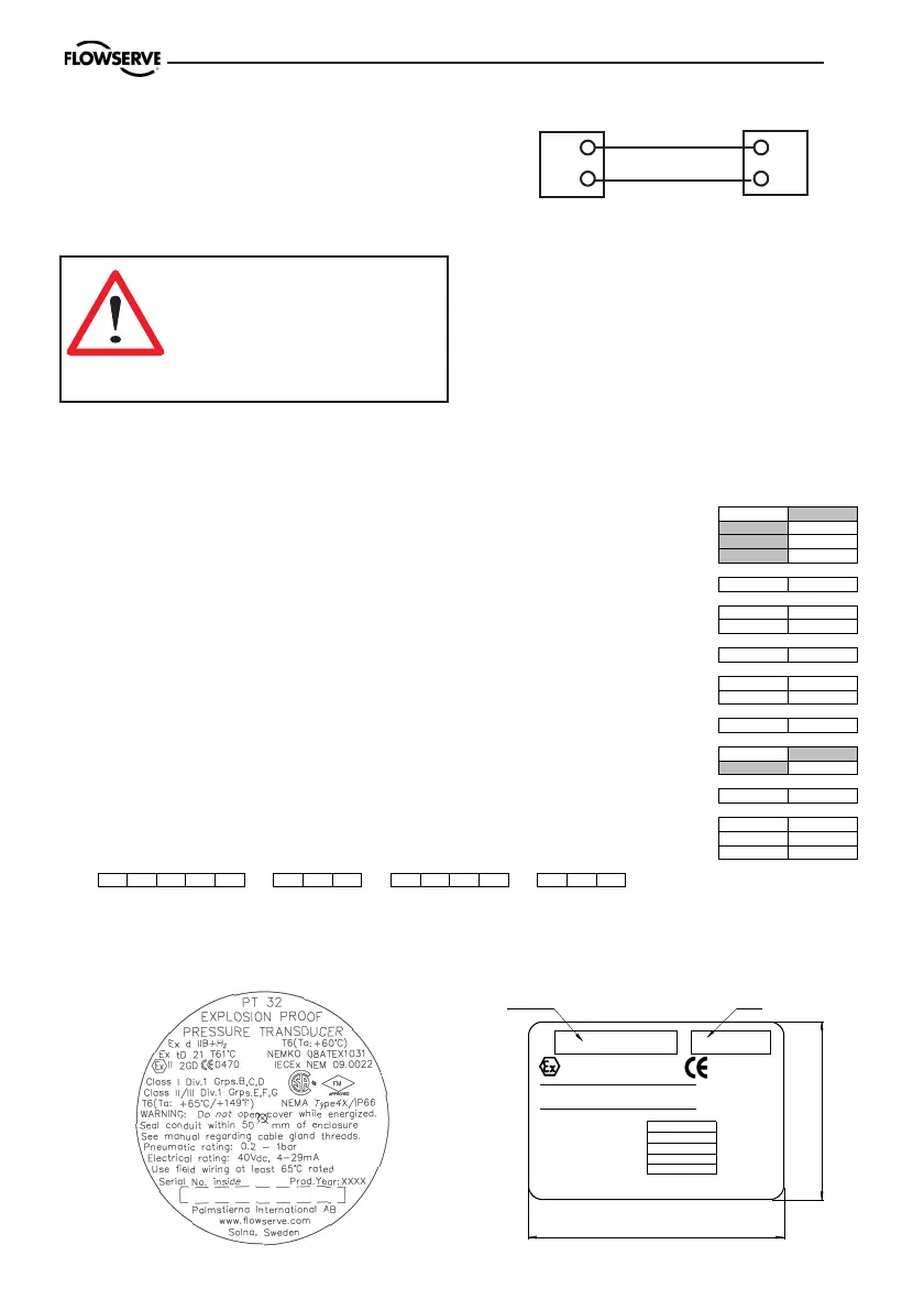
Electrical connections
On positioners with an integral I/P unit,
the electric cables are connected to the
terminals as shown in the figure.
Warning! In a hazardous
environment where there is a
risk of explosion, electrical
connections must comply
with the relevant regulations.
Terminals in
positioner EP3
Output signal
from controller
Hazardous areas
Please see www.pmv.nu/products/ for
copies of certificates for hazardous
approvals.
Signs
Type
Flowserve Sweden, Palmstierna International Solna Sweden
www.flowserve.com
0470
Intrinsically safe when installed
NEMKO 08ATEX1144X
according to document: IP-653
II 2G Ex ia IIC T6/T5/T4
Action:
Logotype
Type: E5-IS
Input Signal:
Input Pressure:
Output Pressure:
Temp. Range:
Prod. year:xxxx
36
25
Model code
A= Model no
PP3XX Linear positioner, Pneumatic
EP3XX Linear positioner, Electropneumatic
EP3IS Linear positioner, Electropneumatic, Intrin.Safe ATEX, IEC
EP3EX Linear positioner, Electropneumatic, Explosion proof ATEX, IEC, FM
B= Function
S Single acting
C= Connections Air - Electrical
M 1/4" NPT - M20x1,5
N 1/4" NPT - 1/2" NPT
D= Surface treatment
U Powder epoxy, black
E= Spindle
05 Male dia. 10 mm
39 Male D type incl nut
F= Cover
PV PMV cover, black, no indicator
G= Input signal
3 3-15 psi
4 4-20 mA
H= Temperature
Z -40 to + 85 deg C
I= Option
X No gauge block
M Gauge manifold 1/8" G
N Gauge manifold 1/8" NPT
P3 - U- PV - Z
PP3 EP3

 Loading...


