5
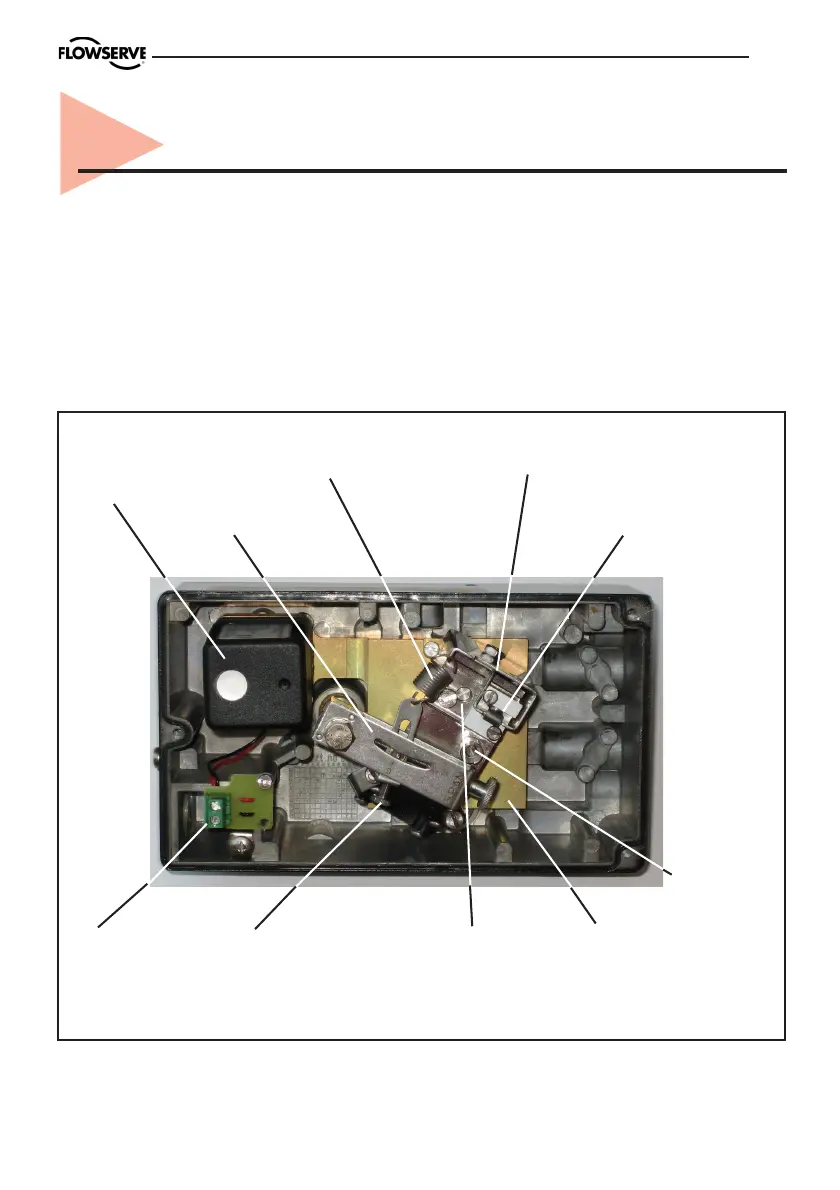
Figure shows P3 positioner with integral I/P converter and cover removed
3. Design
located externally (explosion proof), see
section ”Variants”.
The adjusting screws and knobs are
accessible under the removable sealed alu-
minium cover.
The P3 positioner comprises a basic
module with a single acting valve block. It
also includes a sealed chamber with termin-
als for the electrical input signals.
The I/P unit can be built into the main
housing (as shown in the figure below) or
Span
adjustment
Adjusting
screw, gain
Adjusting screw,
damping
Zero position
adjustment
Balance arm
Flapper nozzle
Feedback spring
I/P
converter
Electrical
connection
Feedback arm
C+
Supply
Input
3-15 psi
➠
➠