E119-P
FW_E119-P_M_v0301-03_EN Page 45
○ Generate any heat that could increase the temperature of the E119-P.
○ Add any electrical energy to the E119-P.
○ Add an empty volume of more than 13.5 cm
3
to the E119-P (e.g. by sealing the opening).
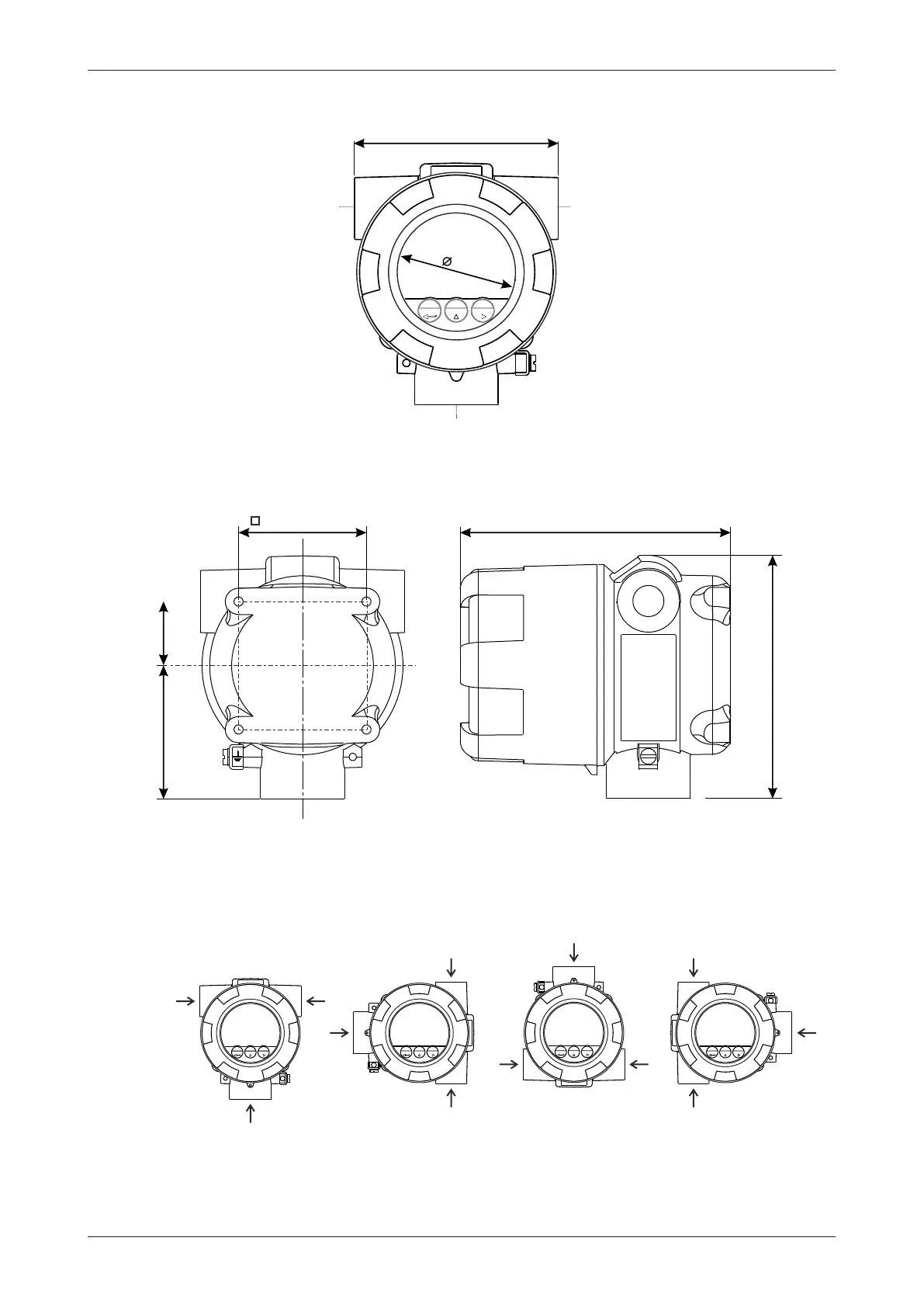
6.3.2 MECHANICAL DIMENSIONS
Right connection
M20x1.5
M25x1.5
½” NPT
¾” NPT
M20x1.5
M25x1.5
½” NPT
¾” NPT
1” NPT
Bottom connection
133mm / 5.24”
148mm / 5.83”
70mm / 2.76”
73mm / 2.87” 35mm / 1.38”
112mm / 4.41”
Left connection
M20x1.5
M25x1.5
½” NPT
¾” NPT
65
Fig.25: Mechanical dimensions of the E-Series enclosure
6.3.3 MOUNTING THE UNIT
The Main Electronics Module (MEM) can be placed into the body in 4 directions (0° – 90° – 180° –
270°). This allows the unit to be mounted in any direction while still allowing the MEM to be installed
in a ‘readable’ position.