FW_F116-P_M_v2201-01_EN.docx
The F116-P has two modes: operational or shelf.
After "shelf" has been selected, the F116-P can be stored for several
years; it will not process the sensor signal; the display is switched off but all
settings and totals are stored. In this mode, power consumption is
extremely low.
To wake up the F116-P again, press the SELECT/ key two times.
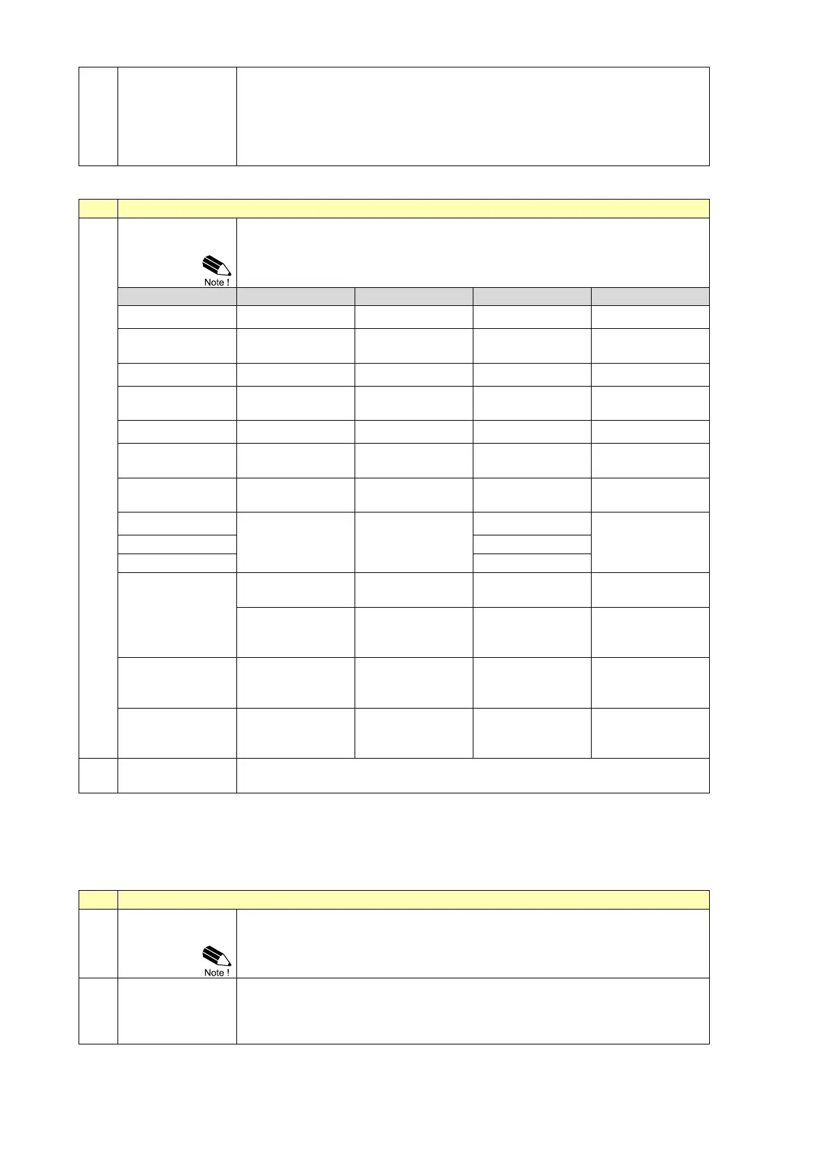
With this setting the type of flowmeter A output is selected. The settings
with LP (low-pass) filter are used to apply a build-in noise reduction.
Selections "active pulse" offer a detection level of 50% of the supply
voltage.
(open collector) less
sensitive
Reed-with low pass
filter
High sensitive coil
input
Sensitive for
interference!
Active pulse input
detection level 8.2 V
DC
Active pulse input
detection level 12 V
DC
Active pulse input
detection level 24 V
DC
Selects the output type of flowmeter B. For description of the options, see
explanation at menu 7.1 SIGNAL A.
3.3.9 MENU 8 - ANALOG OUTPUT
A linear 4-20 mA signal (option AB: 0-20 mA or option AU: 0-10 V) output signal is generated that
represents the (differential or summed) flow rate. The settings for the flow rate influence the analog
output directly. The relationship between the flow rate and the analog output is set with the following
settings.
If the analog output is not used, select disable to minimize the power
consumption (e.g. save battery life-time).
Option AP: When a power supply is available but the output is disabled, a
3.5 mA signal will be generated.
Enter here the flow rate at which the output should generate the minimum
signal (0)4 mA or 0 V - in most applications at zero flow. The number of
decimals shown depend upon setup 2.3. The engineering units/time (e.g.
L/min) are dependent upon setup 2.1 and 2.2.