True-rms Multimeter
Product Familiarization
3
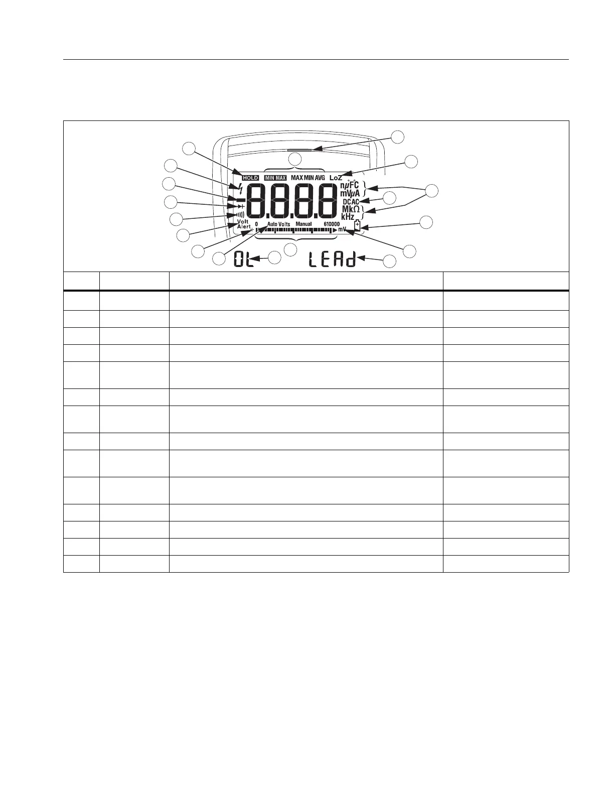
Display
Table 2 is a list of the features for each display.
Table 2. Display
No. Symbol Meaning Model
w
The Meter is in the VoltAlert™ non-contact voltage detect mode. 117
s The Meter function is set to Continuity. 110, 113, 114, 115, 117
R The Meter function is set to Diode Test 113, 115, 117
O Input is a negative value. 110, 113, 114, 115, 117
Z
X Unsafe voltage. Measured input voltage ≥30 V, or voltage
overload condition (OL).
110, 113, 114, 115, 117
K Display hold enabled. Display freezes present reading. 110, 113, 114, 115, 117
M
VWX
MIN MAX AVG mode enabled.
Maximum, minimum, average or present reading displays
110, 113, 114, 115, 117
(Red LED) Voltage presence through the non-contact VoltAlert sensor 117
LoZ
The Meter is measuring voltage or capacitance with a low input
impedance.
113,114, 115, 117
nµF mV µA
MkΩ kHz
Measurement units. 110, 114, 115, 117
DC AC Direct current or alternating current 110, 113, 114, 115, 117
N Battery low warning. 110, 113, 114, 115, 117
610000 mV Indicates the Meter’s range selection. 110, 114, 115, 117
(Bar graph) Analog display. 110, 113, 114, 115, 117
VoltAlert
11
7
17
18
12
13
14
9
6
5
4
3
2
1
16
15
8
10