110/113/114/115/117
Users Manual
4
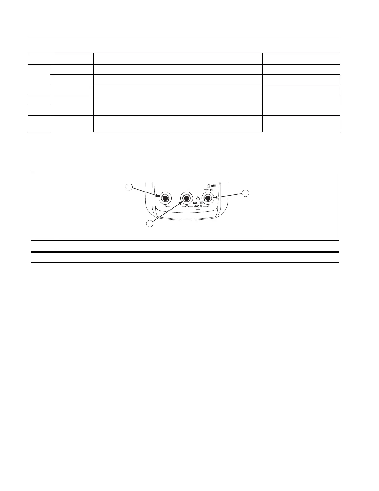
Terminals
Table 3 is a list of terminals on the Meter.
No. Symbol Meaning Model
Auto Volts The Meter is in the Auto Volts function. 114, 117
Auto Autoranging. The Meter selects the range for best resolution. 110, 113, 114, 115, 117
Manual Manual ranging. User sets the Meter’s range. 110, 113, 114, 115, 117
+ Bar graph polarity 110, 113, 114, 115, 117
0L W The input is too large for the selected range. 110, 113, 114, 115, 117
LEAd
W Test lead alert. Briefly displayed whenever the Meter’s function
switch is rotated to or from any A position.
115, 117
Table 3. Terminals
No. Description Model
Input terminal for measuring ac and dc current to 10 A. 115, 117
Common (return) terminal for all measurements. 110, 113, 114, 115, 117
Input terminal for measuring voltage, continuity, resistance, capacitance,
frequency and testing diodes.
110, 113, 114, 115, 117
Table 2. Display (cont.)