Models 110, 111 & 112
Users Manual
6
Making Basic Measurements
The figures on the following pages show how to make basic
measurements.
When connecting the test leads to the circuit or device, connect
the common (COM) test lead before connecting the live lead;
when removing the test leads, remove the live lead before
removing the common test lead.
WWarning
To avoid electric shock, injury, or damage to the Meter,
disconnect circuit power and discharge all high-voltage
capacitors before testing resistance, continuity, diodes,
or capacitance.
Note
In reading AC voltage or current, for the integrated RMS
converter to correctly measure distorted waveforms, reading
settling time increases to several seconds at the low end of
AC voltage and current ranges.
Because inputs below 5% of range are not specified, it is
normal for this meter to display non-zero readings when the
test leads are disconnected from a circuit or are shorted
together.
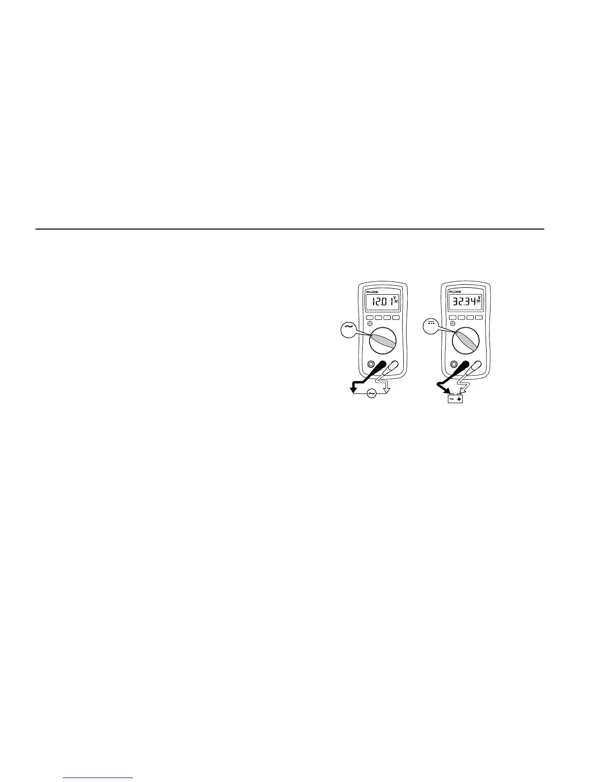
Measuring AC and DC Voltage
Volts DC Volts AC
V
V
aej03f.eps
Understanding AC Zero Input Behavior of True RMS Meters
Unlike averaging meters, which can accurately measure only pure
sinewaves, True RMS meters accurately measure distorted
waveforms. Calculating True RMS converters require a certain
level of input voltage to make a measurement. This is why AC
voltage and current ranges are specified from 5% of range to
100% of range. Non-zero digits that are displayed on a True RMS
meter when the test leads are open or are shorted are normal.
They do not affect the specified AC accuracy above 5% of range.
The input levels that are unspecified are:
• AC voltage: below 5% of 6000 mV AC, or 300 mV AC
• AC current: below 5% of 60 A AC, or 3.00 A AC