®
PN 1608592 March 2001
©2001 Fluke Corporation. All rights reserved. Printed in U.S.A.
1
Models 110, 111 & 112
Multimeters
Calibration Information
Introduction
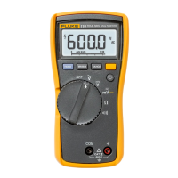
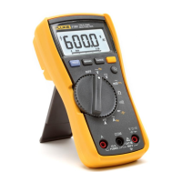
The Fluke Model 110, Model 111, and Model 112 True RMS multimeters (hereafter "the Meter") are
battery-powered, with a 6000-count display and a bar graph.
This calibration information applies to all three models. All figures show the Model 112.
The Meter measures or tests the following:
• AC and DC voltage
• Resistance
• Continuity
• Diodes
• Frequency
• Capacitance
• AC and DC current (Model 111 and Model 112)
"Warning" and "Caution" Statements
A "WWarning" statement identifies hazardous conditions and actions that could cause bodily harm or
death.
A "Caution" statement identifies conditions and actions that could damage the Meter or the equipment
under test.
Unsafe Voltage Symbol
To alert you to the presence of a potentially hazardous voltage, the Y symbol is displayed when the Meter
detects a voltage ≥ 30 V or a voltage overload (OL) condition.
Test Lead Alert
WWarning
Personal injury or damage to the Meter can occur if you attempt to make a
measurement with a lead in an incorrect terminal.
To remind you to check that the test leads are in the correct terminals, LEAd is displayed briefly when you
move the rotary switch to or from
any A position.
These Meters meet CAT III IEC 61010-1-95 standards. The IEC 61010-1-95 safety standard defines four
overvoltage categories (CAT I to IV) based on the magnitude of danger from transient impulses. CAT III
meters are designed to protect against transients in fixed-equipment installations at the distribution level.