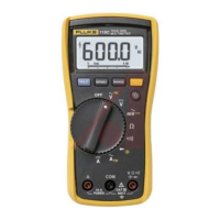
Models 110, 111 & 112
Calibration Information
16
User-Replaceable Parts
User-replaceable parts are shown in Table 6.
Table 6. User Replaceable Parts
2
3
4
5
1
6
8
7
9
10
11
12
aej16f.wmf
Item Description Part No
1 Holster 1579321
2 Tilt stand 1566954
3 Battery door 1572523
4 9 V Alkaline battery, ANSI 1604A/IEC 6LR61 614487
5 Case bottom 1566946
6 W F1 Fuse, 11 A, 1000 V, FAST - Minimum interrupt rating 17,000 A (Models 111 and 112) 803293
7 Elastomeric connector 1569475
8 Rubber spacer 1568778
9LCD 1555497
10 LCD mask (Model 110) 1567724
LCD mask (Model 111) 1567713
LCD mask (Model 112) 1580678
11 Keypad (Models 110 and 111) 1566794
Keypad with backlight button (Model 112) 1566782
12 Case top (Model 110) 1608241
Case top (Model 111) 1608234
Case top (Model 112) 1608229
W To ensure safety, use exact replacement only.

 Loading...