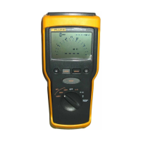
Getting Started
Scope Connections and Grounding
7
Scope Connections and Grounding
For single input measurements use the Red Shielded Test
Lead on Input A. For measurements on two different
signals, additionally use the Gray Shielded Test Lead on
Input B.
For low frequency measurements and high signal levels,
use the Black COM (Common) Input as single ground.
Figure 3 shows this.
Figure 3. Grounding with Unshielded Ground Lead.
For measurements at higher frequencies or low levels, use
both Shielded Test Leads with Short Ground Leads
instead of using the COM Input.
Bear in mind that the Short Ground Leads must be
connected to the same potential! Refer to Figure 4.
Figure 4. Grounding with Short Ground Leads
Warning
To avoid electrical shock or fire, use only one
COM (common) connection , or ensure that
all connections to COM
are at the same
potential.
Note:
Fluke 124 is supplied with a 10:1 Oscilloscope
Probe. Use of a Probe is recommended when
you measure high frequency signals in circuits
with a high impedance. The Probe such as
supplied matches with the Test Tool without
additional high frequency adjustment.
For grounding of the Probe, use a Short Ground
Lead such as also used with the Shielded Test
Leads.