175, 177, & 179
Calibration Information
14
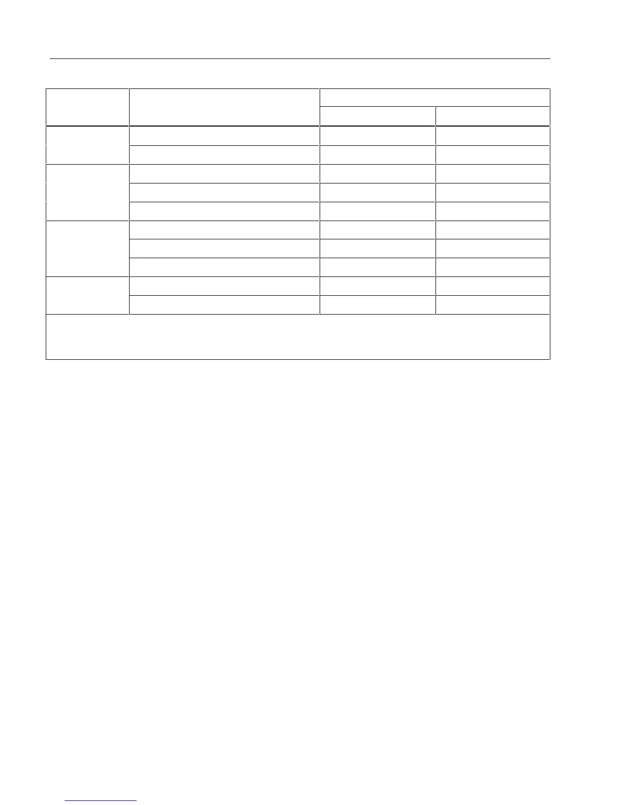
Table 4. Performance Tests 177/179
Meter Response
Test 5520 Output Lower Limit Upper Limit
4.0 A 45 Hz 3.937 A AC 4.063 A AC
J
AC Amps
9.0 A 1 kHz 8.84 A AC 9.16 A AC
0.003 A 45 Hz 2.93 mA AC 3.07 mA AC
0.05 A 1 kHz 49.22 mA AC 50.78 mA AC
F
AC Milliamps
0.4 A 1 kHz 393.7 mA AC 406.3 mA AC
0.003 A, 0 Hz 2.94 mA DC 3.06 mA DC
0.05 A 49.47 mA DC 50.53 mA DC
mI
DC Milliamp
1
−0.4 A −404.3 mA DC −395.7 mA DC
4.0 A 3.957 A DC 4.043 A DC
I
DC Amps
1
−9.0 A −9.12 A DC −8.88 A DC
1. Press the YELLOW button to select this function.
2. Does not include test lead resistance.
3. Be sure to use correct cable.
Calibration
Perform the calibration adjustment procedures if the Meter fails the performance test.
The meter buttons behave as follows when the calibration mode is enabled:
H
Press and hold this button to test the present function. This measurement is uncalibrated and
may be inaccurate. This is normal.
M
Press and hold this button to display the required input.
R
Press this button to skip the present calibration step without accepting the input signal.
Note
If a calibration step is skipped, the remaining calibration procedure may be invalidated.
B
Press this YELLOW button to store the calibration value and advance to the next step. This
button is also used to exit calibration mode after the calibration sequence is complete.
Calibration Procedure
Use the following steps to calibrate the meter:
1. Switch the meter to volts AC (C).
2. Turn the meter over and find the calibration seal located near the top of the meter. Refer to Figure 4.
3. With a small probe, break the calibration seal and press the calibration button for 1 second. The meter
will beep and change to the calibration mode. The display reads C-01, designating the first calibration
step. The meter remains in calibration mode until the rotary switch is turned off.
4. Proceed through the calibration steps by entering the input value listed in the table for each step.
5. After each input value is applied, press the YELLOW button to accept the value and proceed to the
next step (C-02 and so forth).
 Loading...