15B+/17B+/18B+
Calibration Manual
16
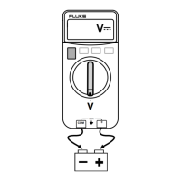
• Connect the UUT signal input terminal to the calibrator (5522A or other
calibrator.)
icr07.eps
Figure 4. Calibration Connections
4. To put the UUT in calibration mode, use a small probe to push the calibration
button (CAL1) See Figure 5 for 15B+ and 17B+ and Figure 7 for 18B+.
Calibration for 15B+ and 17B+
For each function in Table 7:
1. Turn the rotary selection knob to the function to be calibrated.
2. Set calibrator output for the appropriate signal.
3. Wait 4 seconds for the reading to stabilize then push to confirm and
forward next step.
4. On the PCB, short CAL1 and WP6 together. See Figure 5.