27
Service Manual
3-8
Top Case/Digital
PCB Subsection
Button-Up
Subsection
Main Board
Subsection
MP2
MP19
U3
MP2 (2PL)
MP18
H2 (2PL)
H1
MP4
MP7
MP1
MP5
MP6
S3
A2
H5 (4PL)
MP9
MP8
A1
MP3
H4 (3PL)
MP17
H8 (2PL)
H9 (2PL)
F1
F2
H3 (4PL)
F1
F2
MP61
MP15
H6
BT1
MP13
MP10
MP12
MP11
MP21
H7 (4PL
)
MP16
MP14
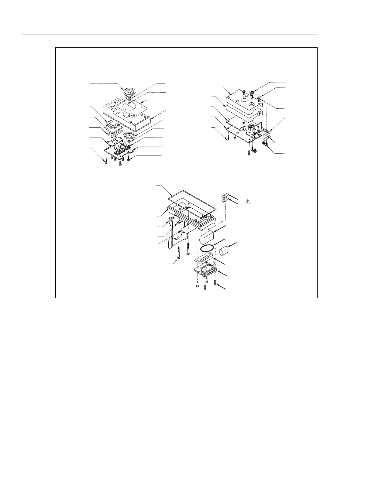
aac04f.eps
Figure 3-2. Disassembly
Most maintenance procedures require at least partial instrument disassembly. The
following procedure (illustrated in Figure 3-2) provides complete step-by-step
disassembly instructions to gain access to any assembly. Complete disassembly is not
required to gain access to most assemblies; the following procedure contains notes that
explain which maintenance procedures are possible at various levels of disassembly.
1. Turn the function switch to the upper OFF position.
2. Lift the tilt bail up about 1 inch up from the back of the instrument, then gently pull
out the ends of the tilt bail and remove it.
3. Remove the four Pozidriv
®
machine screws (H6) that hold the battery cover (MP14)
to the bottom case, then lift the battery cover and battery spacer out of the
instrument.
4. Disconnect and remove the battery.
5. Unsnap the battery spacer from the battery cover.