Maintenance
General Maintenance Information
3
3-9
6. Remove the old O-ring (MP15). Clean the O-ring surfaces of the battery cover and
the instrument case. Install the battery holder on the battery cover, then install the
new O-ring.
7. Remove the four Pozidriv
®
screws (H7) and rubber washers from the bottom case.
8. Lift the bottom case off the instrument, and remove the O-ring (MP13) between the
top and bottom cases. (Always install a new O-ring prior to reassembly.)
9. At this point, all calibration adjustments are accessible through the openings in the
side of the pca shield. Refer to the calibration adjustment procedure later in this
chapter to calibrate the instrument.
10. Remove the four Phillips-head screws (H3) at the bottom of the pca that connect the
pca to the input terminals molded into the top case.
11. Carefully lift the upper end of the main pca and shield assembly to disconnect the
assembly from the digital pca, then lift the main pca and shield assembly clear of the
case.
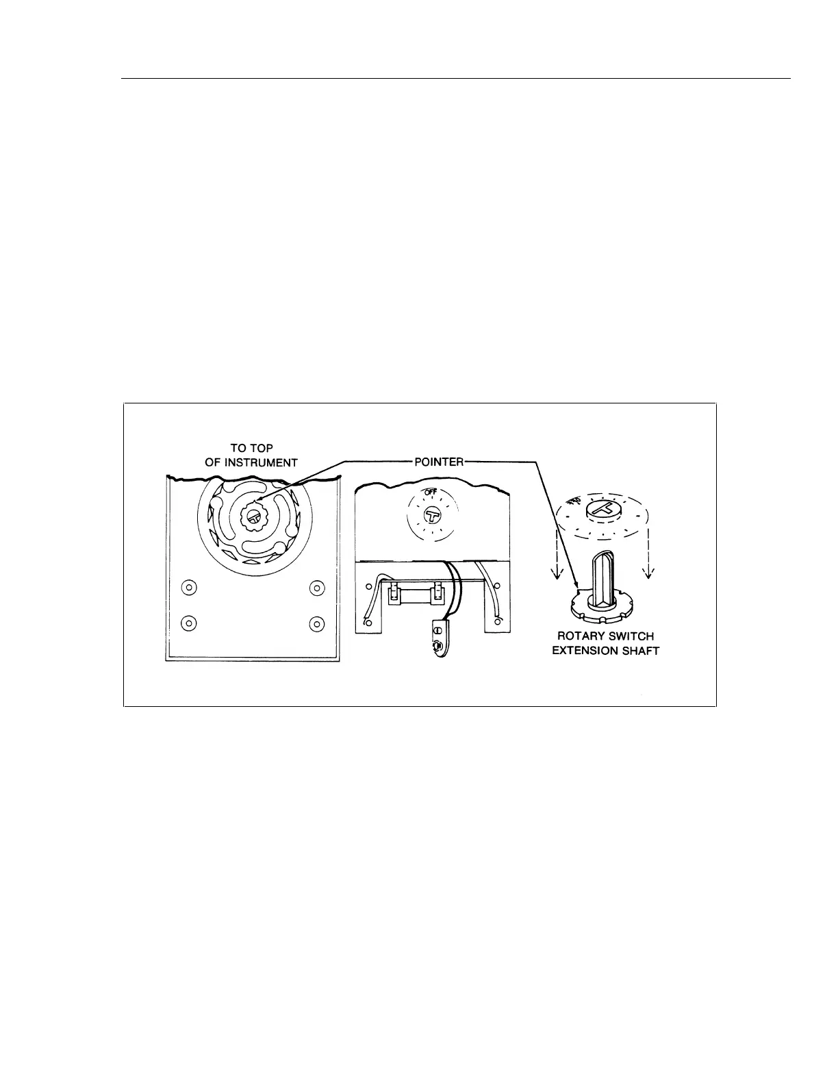
aac05s.tif
Figure 3-3. Switch Extension Shaft Installation
12. Note the position of the rotary switch extension shaft (MP17). With the rotary switch
in the OFF position, the single small pointer on the base of the extension shaft is
pointed toward the top of the instrument. Refer to Figure 3-3.
13. Lift the rotary switch extension shaft (MP17) off the rotary switch shaft (the shaft on
MP2).
14. Remove the E-ring retainer (MP6) and the detent spring (MP5) from the rotary
switch shaft.
15. Pull the rotary switch knob (MP2) out from the front of the top case (MP1). Take
care not to loose the Teflon bearing washer (H1) under the knob.
16. To replace the O-ring (MP4) on the rotary switch shaft, cut off the existing O-ring
without scratching the metal shaft. Clean the shaft thoroughly, and slide a new O-
ring over the shaft into the groove on the shaft.