Multifunction Electrical Tester Calibrator
Electrical Specifications
7
Line/Loop Impedance Source
Range................................................................. 25 mΩ to 1.8 kΩ
Resolution ......................................................... 16 discrete values
Minimum test voltage/current.......................... 10 V/10 mA
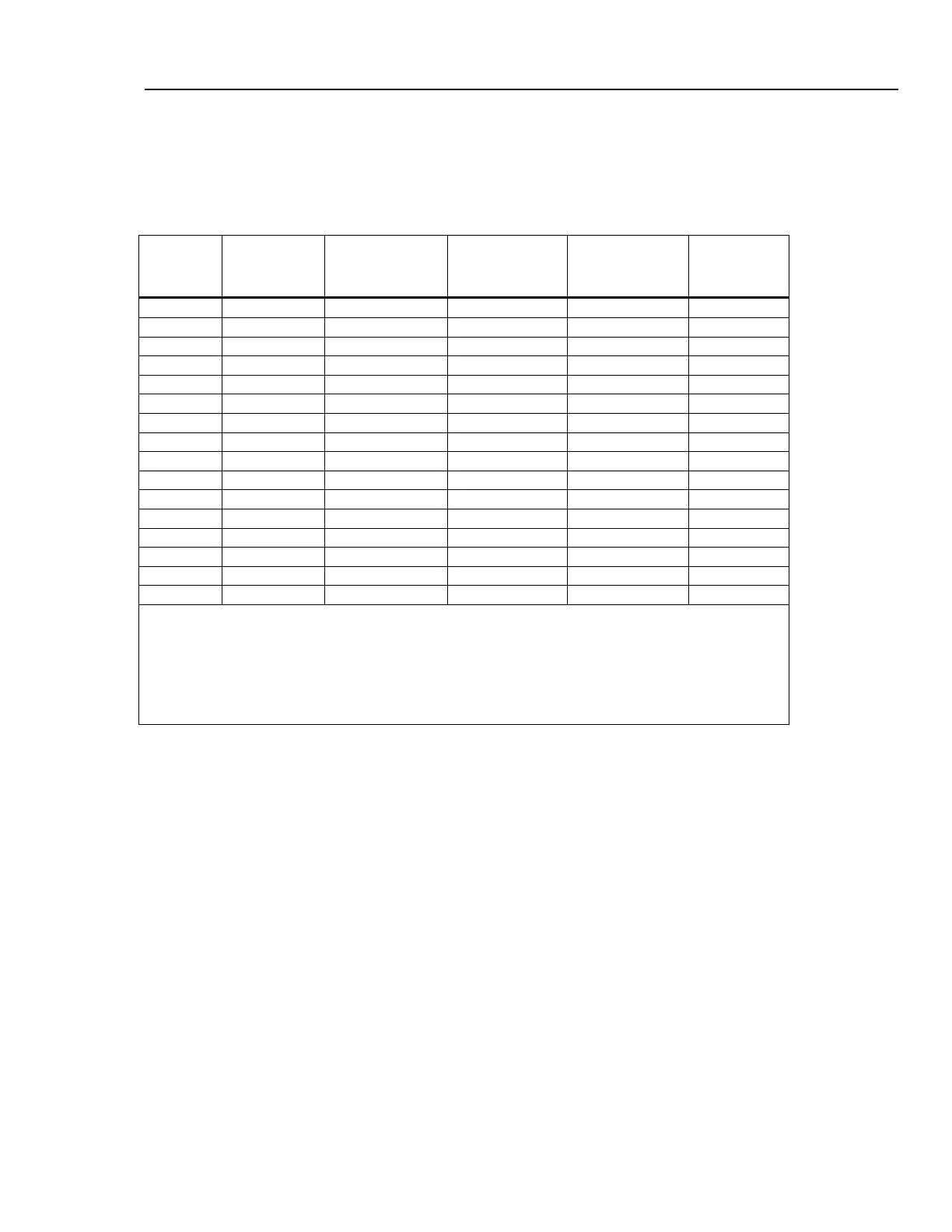
Uncertainty and Maximum Ratings
Nominal
Resistance
Value
Deviation from
Nominal Value
Absolute
Uncertainty of
Characterized Value
(tcal ±5 °C)
Maximum
Continuous Test
Current
AC rms or DC
[1]
Maximum
Short-term
Test Current
AC rms or DC
[2]
Test Current
Uncertainty
25 mΩ ±50 % ±5 mΩ
30 A 40 A 1.5 % + 0.7 A
50 mΩ ±50 % ±5 mΩ
28 A 40 A 1.5 % + 0.5 A
100 mΩ ±30 % ±5 mΩ
25 A 40 A 1.5 % + 0.35 A
330 mΩ ±20 % ±7 mΩ
14 A 40 A 1.5 % + 0.3 A
500 mΩ ±10 % ±8 mΩ
10 A 40 A 1.5 % + 0.2 A
1 Ω ±10 % ±10 mΩ
8 A 40 A 1.5 % + 150 mA
1.8 Ω ±10 % ±18 mΩ
6 A 30 A 1.5 % + 100 mA
5 Ω ±10 % ±30 mΩ
3.2 A 21 A 1.5 % + 70 mA
10 Ω ±10 % ±60 mΩ
2.0 A 15 A 1.5 % + 50 mA
18 Ω ±10 % ±100 mΩ
1.5 A 10 A 1.5 % + 30 mA
50 Ω ±10 % ± 300 mΩ
0.8 A 5.0 A 1.5 % + 20 mA
100 Ω ±10 % ± 500 mΩ
0.5 A 3.0 A 1.5 % + 10 mA
180 Ω ±10 % ± 1 Ω
0.25 A 1.35 A 1.5 % + 5 mA
500 Ω ±10 % ± 2.5 Ω
0.1 A 0.6 A 1.5 % + 3 mA
1 kΩ ±10 % ± 5 Ω
0.05 A 0.3 A 1.5 % + 2 mA
1.8 kΩ ±10 % ± 10 Ω
0.025 A 0.15 A 1.5 % + 2 mA
Notes:
[1] Test currents up to 30 % of maximum continuous test current can be applied to the Calibrator with no time limitation. Test
current between 30 % and 100 % of the maximum continuous test current can be applied to the Calibrator for a limited time.
Minimum period of full current load is 45 seconds. The Calibrator calculates the allowed time period and when exceeded, the
output connectors are disconnected.
[2] Maximum short term test current is defined as the rms value of halfwave or fullwave test current flowing through the UUT.
Maximum time of test is 200 ms. A time interval of 200 ms represents 10 full waves of power line voltage at 50 Hz and 12 full
waves at 60 Hz.
Test Current Measurement
Type of recognized test current ...................... Positive impulse (halfwave), negative impulse (halfwave),
symmetrical (fullwave).
Range................................................................. 0 to 40 A ac + dc rms
Resolution ......................................................... 1 to 100 mA depending on test current and resistance output
Prospective Fault Current
Range................................................................. 0 to 10 kA
Correction Manual Mode
Residual Impedance Range ............................. 0 to 10 Ω
Resolution ......................................................... 1 mΩ
Uncertainty ........................................................ Uncertainty in manual (MAN) mode is the uncertainty of selected
resistance value. See table above. Also, the uncertainty of the
manually entered correction should be taken into consideration.
Correction Scan Mode
Residual Impedance Range ............................. 0 to 10 Ω
Resolution ......................................................... 1 mΩ
Uncertainty ........................................................ (1 % +15 mΩ) + uncertainty of selected resistance value.

 Loading...


