5320A
Getting Started Manual
14
Table 3. Measurement Input Fuses
Input Fuse Fluke Part No.
RCD F3.15L 250V (5 x 20 mm) 2743508
Leakage Current F100mAL 250V (5 x 20 mm) 2743513
Meter F20L 500V (6.3 x 32 mm) 2743536
Loop/Line Impedance T4AL 250V (6.3 x 32 mm) 2743524
Connecting to Line Power
XWWarning
To avoid shock hazard, connect the factory supplied three-
conductor line power cord to a properly grounded power
outlet. Do not use a two-conductor adapter or extension cord;
this will break the protective ground connection. If a two-
conductor power cord must be used, a protective grounding
wire must be connected between the ground terminal on the
rear panel and earth ground before connecting the power cord
or operating the instrument.
After you verify that the line voltage selection switches are set to the correct positions,
verify that the correct fuse for that line voltage is installed. Connect the Calibrator to a
properly grounded three-prong outlet. Table 4 lists the line power cord types available
from Fluke.
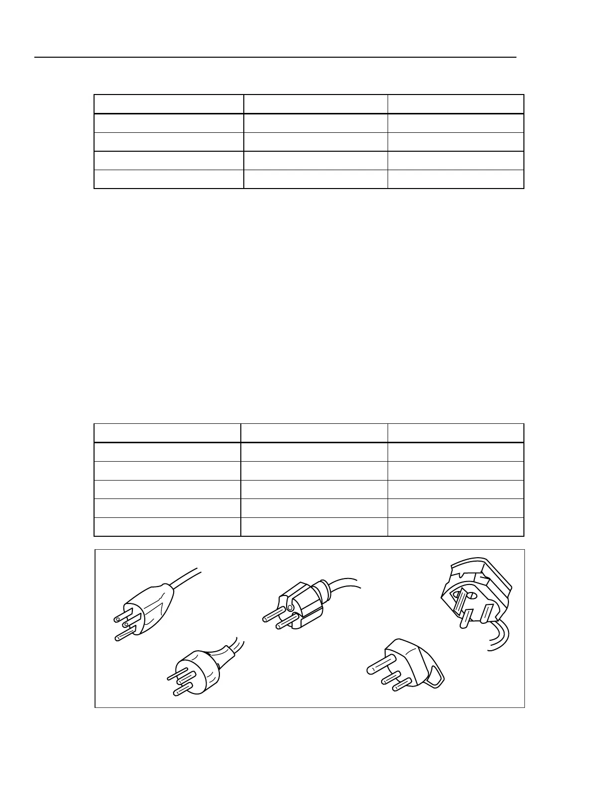
Table 4. Line Power Cord Types Available from Fluke
Type Voltage Fluke Part No.
North America/Japan 120 V 2743310
Universal Euro 240 V 2743331
United Kingdom 240 V 2743322
Australia/China 240 V 2743346
South Africa/India 240 V 2743354
North America/Japan
Universal Euro
United Kingdom
Australia/China
SouthAfrica
ehq050.eps
Figure 1. Line Power Cords Types Available from Fluke

 Loading...


