5320A
Getting Started Manual
16
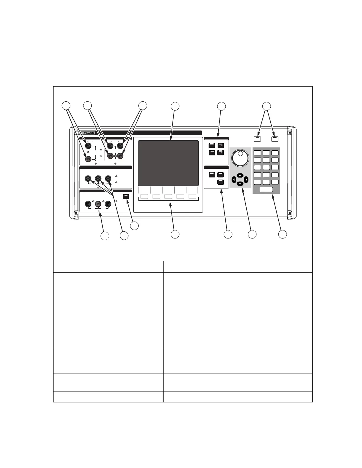
Front-Panel Features
Table 5 lists the controls and terminals found on the front panel.
Table 5. Front-Panel Features
N
L
PE
L1 L2 L3HES
OUTPUT
Z
L
, Z
GND
,
RCD
HI
LO
HI
LO
METER
METER
Z
L
Z
GND
Z
L
, Z
GND,
RCD
OUTPUT
RCD
LO
V
mA
HI
1
4
7
.
2
5
8
+/-+/-
3
0
6
9
EXP
BKSP
CANCEL
ENTER
OPER
STBY
5320A
MULTIFUNCTION ELECTRICAL TESTER CALIBRATOR
V
A
COM
LO
LO - SENSE
, HI ,
mA
V
INPUT
1500V PK
MAX
50V PK
MAX
280V
RMS
MAX
280V
RMS
MAX
20V PK
20V PK
CAT I
1000V
CAT II
600V
RMS MAX
20V PK
30A
RMS
MAX
20V PK
1 2 3
7 9
1311108
4
5
6
12
elv1.eps
Item Description
A OUTPUT Terminals XWWarning
Electric shock hazard. Lethal voltages are either applied
to or supplied from these terminals when the Calibrator
is operating. Ensure the Calibrator and UUT is in standby
mode before connecting or removing leads to these
terminals. Up to 600 V ac or dc is supplied from these
terminals when the Voltage function is operating.
Provides connection points for ac and dc voltage and current
as well as high resistance.
B LOΩ Terminals Provides connection points for low resistance. Use these two
source terminals for 2-wire ohms measurements. They are
also source terminals for 4-wire measurements.
C LOΩ Sense Terminals Provides connection points for the sensing of low resistance
in 4-wire measurements.
D M Selects the meter function.

 Loading...


