FUNCTION AND RANGE HINTS AND COMMENTS
When reset is depressed, the display and counting
registers are cleared. When reset is released, a new
measurement is started. The Measuring-time-, Func-
tionand display hold- settings are not affected.
If the TOT A function is selected, the RESET/LOCAL
key functions as a START/STOP key. One press
starts the counting and the next press stops it. A long
depression results in reset.
When the counter is controlled from the GPIB-Bus,
the LOCAL key can be disabled via the ’Local Lock
out’ command.
Display hold freezes the display, but not until the
measurement in process has been finished. A new
measurement can always be initiated via the RESET
key.
Store A
0
is used to store the constant used in func-
tions FREQ A/A
0
and FREQ A-A
0
. The procedure is
described under FUNCTIONS, FREQ A/A
0
.
Use this input for all functions except FREQ B.
Range: 10 Hz to 160 MHz
Impedance: 1 M //30 pF
Min. pulse duration:4 ns
At higher frequencies; use a 50 Ω termination type
PM 9585 to avoid interference caused by impedance
mis match.
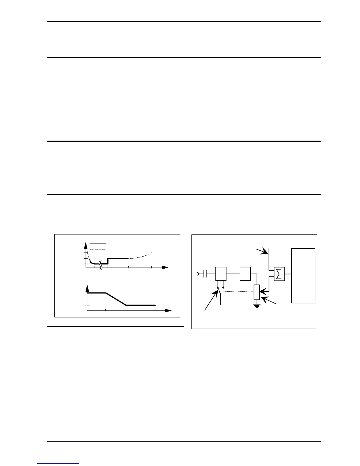
The illustration below shows which function block
each of the input controls affect.
This is the HF-input which must be used when the
FREQ-B function is selected. If the Frequency
Counter does not include the Input-B option, the BNC-
connector is replaced by a plastic plug.
Range:
70 to 1300 MHz.
Impedance:
50Ω
Sensitivity:
10 mV
RMS
up to 900 MHz,
15 mV
RMS
900-1100 MHz
and 40 mVRMS above.
Max voltage:
12 V
RMS
8 V
0 440 Hz 1 MHz 120 MHz
2
0
H
z
20 mV
40 mV
60 mV
0 30 MHz 120 MHz 160 MHz
AC Spec.
DC Spec.
Typically
RMS
Max voltage
350 V
DC+AC
peak
Sensitivity
Attenuator
Sensitivity range switch
Counting
logic
Trigger level offset
Input-A
Filter
Sensitivity
control
Figure 7.
Input circuit block diagram.
OPERATING INSTRUCTIONS Page: 17
PM 6669 - OPERATORS MANUAL