Do you have a question about the FLYGT APP700 and is the answer not in the manual?
Provides a general overview of safety information and warnings.
Specifies the required sheltered, well-ventilated, and nonhazardous installation environment.
Defines the acceptable operating temperature range for the unit.
Emphasizes suppressing equipment causing serious electrical or magnetic disturbances.
Highlights the need to observe all government regulations and directives.
Details electrical safety, grounding, and power disconnection procedures.
Advises on managing harmonic interference from VFD drives and other sources.
Explains Xylem's warranty terms for product defects in design, materials, or workmanship.
Lists conditions such as maintenance, installation, and usage not covered by the warranty.
Specifies that all product work must be performed by certified electricians or authorized mechanics.
Highlights correct monitoring equipment usage and consequences of improper use.
States that product modifications require prior consultation with Xylem.
Emphasizes using original spare parts for compliance and warranty validity.
Instructs users to contact their Xylem representative for warranty claims.
Clarifies Xylem's support for tested and approved products only.
Explains the meaning of warning symbols used in product information documents.
Explains symbols found directly on the product, indicating hazards like high voltage.
Lists crucial checks before mounting the unit, including cubicle type and temperature range.
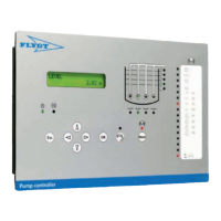
Provides step-by-step instructions for mounting the operator panel in an equipment cabinet.
Shows the physical dimensions and mounting requirements for the operator panel.
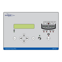
Provides steps for locating and mounting the I/O unit, considering proximity to power sources.
Shows the physical dimensions and mounting details for the I/O unit.
Refers to a separate level sensor manual for mounting instructions.
Highlights the importance of cable management for minimizing field disturbances.
Lists potential sources of disturbance and factors affecting system susceptibility.
Recommends overvoltage and lightning protection for power and telecommunications cables.
Illustrates recommended practices for avoiding electric and magnetic disturbances.
Provides a detailed drawing showing the terminal connections for the RTU system.
Explains how to connect passive and active sensors delivering 4-20 mA current.
Illustrates the connection diagrams for analog inputs for passive and active sensors.
Details connecting digital inputs, setting options for contact functions.
Advises on using external power supply for active inputs to avoid disturbance.
Outlines general steps for connecting digital inputs according to sensor type.
Shows the connection drawing for wiring active sensors to digital inputs.
Provides steps and example for connecting passive sensors to digital inputs.
Details the terminal assignments for digital input signals.
Details connecting digital outputs, including warnings about high voltage.
Outlines general steps for connecting digital outputs.
Shows the connection diagram for relay and semiconductor digital outputs.
Details the terminal assignments and ratings for digital outputs.
Explains how to connect remote I/O units using a SIOX bus expansion.
Provides steps to install a SIOX Expansion Card and connect external I/O units.
Lists precautions for connecting the power supply, including fuse protection and noise filters.
Provides step-by-step instructions for connecting the 24V DC power supply.
Details the specifications for the external 24V DC power supply input.
Advises on proper earthing and connecting overvoltage protection to grounding points.
Lists various modem types (GSM, dial-up, dedicated line) and their functions.
Provides general steps for connecting the modem to COM ports and its power supply.
Explains the meaning of the green and red lights on the communication status LED.
Provides steps to test communication by checking cables and modem status.
Details how to test the level sensor signal by checking voltage and current.
Describes how to test digital inputs by activating signals and checking LEDs.
Provides steps to test the power supply unit connections and voltage range.
Covers hardware specifications including environment, frontal unit, and I/O unit details.
Details cable length, minimum bend radius, and connector type.
Lists standard accessories available for the unit, such as software and modems.
Encompasses electrical data for digital inputs/outputs, analog inputs, communication, power supply.
Lists the unit's compliance with various EMC, LVD, CSA, and UL standards.
| Brand | FLYGT |
|---|---|
| Model | APP700 |
| Category | Control Unit |
| Language | English |