Terminal Input signal no./Description
+33/–34 16
+35/–36 Internal 24V DC power supply to digital input signals.
Signal requirements
The signal requirements are:
• Logical 0 = –3 to +5V.
• Logical 1 = 11–30V, 6–30mA.
Connect Digital Outputs
WARNING:
Always take care when making connections and carrying out service work; these outputs
may be at high voltage.
General instruction
Connect the digital outputs according to the following instructions:
• Connection drawing, and
• Terminals.
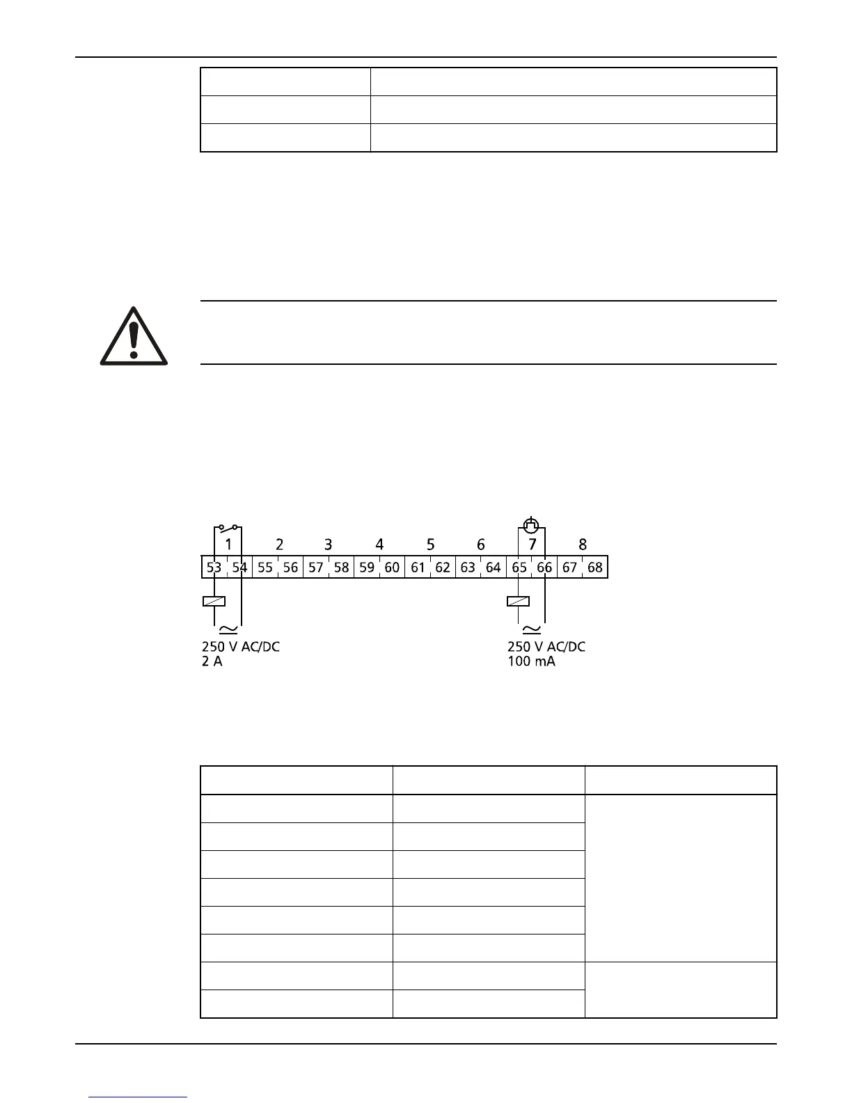
Connection drawing
This is a connection drawing of the digital outputs.
Figure 10
Terminals
This table gives an overview of the terminals for digital outputs.
Table 8
Terminal
Output signal no. Type/Rated for
53/54 1 Relay output
2A, 250V, AC/DC
55/56 2
57/58 3
59/60 4
61/62 5
63/64 6
65/66 7 Semiconductor output
100 mA, 250V AC/DC
67/68 8
Connect Inputs and Outputs
14 Hardware for APP700 and APX700 Installation