Terminals
This table gives an overview of the terminals for analog inputs.
Table 5
Terminal Input signal no./Description
+39/–40 Internal 24V DC power supply for analog input signals.
+41/–42 1
+43/–44 2
+45/–46 3
+47/–48 4
49/50
• Terminal 49 is functional earth (ground).
• Terminal 50 is the functional earthing of the shield in all shielded cables.
Connect Digital Inputs
Introduction
The RTU is usually set for normally open contact functions to all 16 digital inputs (from
terminals 3 to 34). If normally closed contact functions are required, this can be set in the
program.
Power supply
Active sensor: It is best to use an external power supply for the inputs, to avoid electrical
disturbance.
Passive sensor: An internal power supply should only be used if a pair of voltage free
normally open or normally closed contacts is available on the peripheral equipment.
General instruction
Connect the digital inputs according to the following instructions:
• Connect active sensor,or
• Connect passive sensor,and
• Terminals
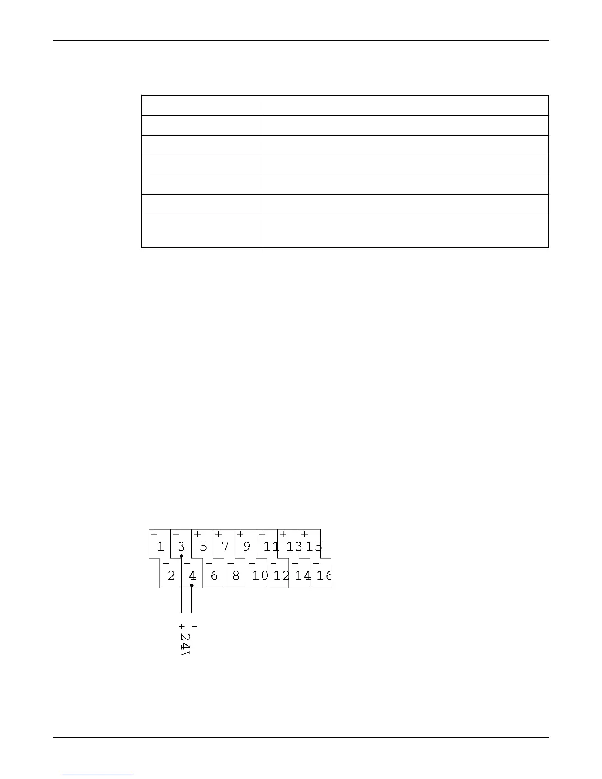
Connect active sensor
Follow this connection drawing to connect active sensors to the digital inputs.
Figure 8
Connect Inputs and Outputs
12 Hardware for APP700 and APX700 Installation