31
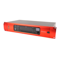
REDNET 5
UNIT CONNECTIONS AND FEATURES
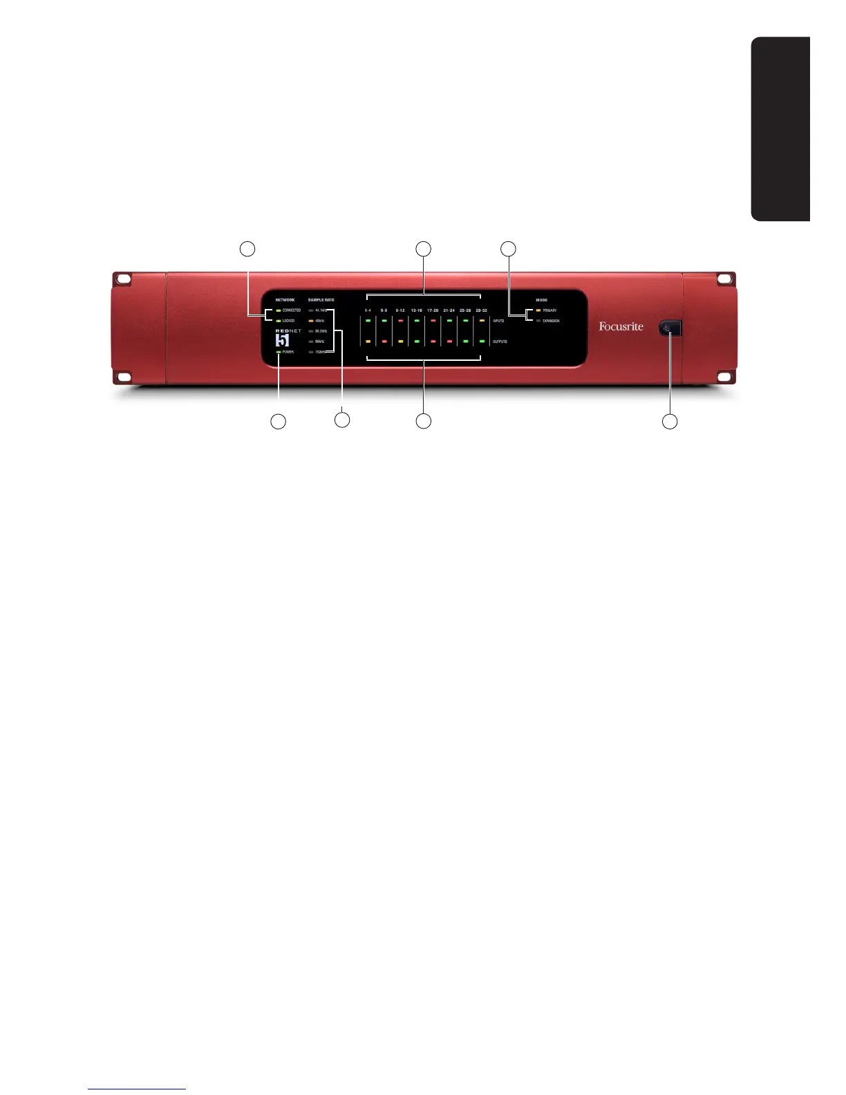
RedNet 5 - Front Panel
1. AC Power switch
2. INPUTS – inputs to the network (i.e., outputs from Pro Tools|HD*). Eight tricolour LEDs
indicating the signal level in four consecutively-numbered channels; the colour indicates the
highest signal in the four. Individual LEDs indicating signal level at each analogue input:
• • Green: signal present
• • Amber: -6 dBFS
• • Red: 0 dBFS
3. OUTPUTS – outputs from the network (i.e., inputs to Pro Tools|HD*). Eight LEDs indicating the
signal level in the output channels; these function in the same manner as the input channel
LEDs [2]
4. NETWORK status flags – two green LEDs confirming network status:
• • CONNECTED – illuminates when the unit is connected to an active Ethernet network
• • LOCKED – illuminates when a valid sync is received via the network or an external
source
5. SAMPLE RATE indication – five yellow LEDs; only one of these (44.1 kHz, 48 kHz, 88.2 kHz,
96 kHz, 192 kHz) will be lit at a time, to confirm the sample rate that the system is running at.
6. MODE indicators – two yellow LEDs confirming the Pro Tools interface mode:
• • PRIMARY – the normal operating mode, in which RedNet 5 appears to Pro Tools as
two external 16 channel interfaces.
• • EXPANSION – this mode should be selected from RedNet Control when the rear Panel
EXPANSION port is in use. RedNet 5 will now appear to Pro Tools as a single 16 channel
interface. This mode should also be used when RedNet 5 is connected to the expansion port
of a 16 channel Pro Tools|HD device.
7. POWER LED
REDNET 5
4
2
3
5
1
6
1
*including Pro Tools|HD, Pro Tools|HDX and Pro Tools|HD Native hardware