5
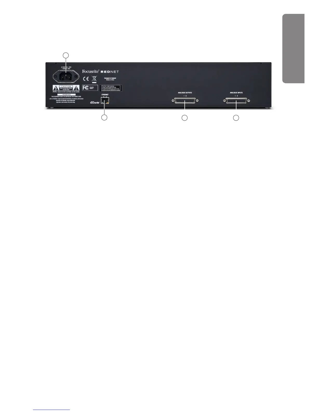
RedNet 1 - Rear Panel
6. ANALOGUE INPUTS 1-8 – 25-pin female Dsub connector for connecting up to 8 analogue
sources to the RedNet system. All inputs are electronically balanced. See page 7 for connector
details.
7. ANALOGUE OUTPUTS 1-8 – 25-pin female Dsub connector with 8 analogue outputs from the
RedNet system. All outputs are electronically balanced. See page 7 for connector details.
8. ETHERNET – RJ45 network socket. Use a standard CAT 6 cable to connect this socket to a
local Ethernet switch to connect the RedNet 1 to the RedNet network. The socket has integral
LEDs which illuminate to indicate connection to an active network port, and network activity.
See page 8 for connector details.
9. AC mains – standard IEC receptacle for connection of AC mains. RedNet 1 has a ‘Universal’
PSU, enabling it to operate from any supply voltages between 100 V and 240 V.
67
8
9
REDNET 1