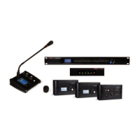
2.- PHANTOM POWER SUPPLY MODULE
a
.- DC 48 V: allows the phantom power supply of each input channel to be
a
ctivated/deactivated.
b.- Microphone Sensitivity: allows the microphone sensitivity to be adjusted.
c.- Polarity: allows the input signal phase to be inverted 180º.
3.- INPUT/OUTPUT CHANNELS
a.- Input/output channel selector (CH1 - CH12).
b.- Mute: silences the corresponding input/output channel.
c.- Signal level digital fader (-80 a +15dBu).
d.- LED indicator of input/output channel signal level.
e.- Displays the gain value applied to the input/output channel.
4.- DELAY MODULE
a.- Delay: delay applied to the signal from the corresponding input/output
channel, in ms.
b.- Bypass: the input signal is not processed and is diverted to the next
processing module.
5.- EQUALIZATION MODULE
High and low pass filters to eliminate frequencies above or below the
established cutoff frequency.
a.- Freq.: cutoff frequency.
b.- Type: type of filter applied: Bessel, Linkwitz or Butterworth.
5-band parametric equalization. Allows the input signal spectrum to
be modified graphically or by entering the required values manually.
c.- Frequency: central frequency.
d.- Qfact: filter quality factor. The greater the value, the smaller the range of frequencies that are affected.
e.- Flat: all the equalization parameters are restored to their original value.
f.- Bypass: the input signal is not processed and is diverted to the next processing module.
g.- Gain: gain elevation or attenuation in the established central frequency.
h.- Type: type of filter; peak, low pass or high pass.
i.- Bypass 1~5: allows the processing of filters 1 to 5 to be cancelled without using the general bypass.
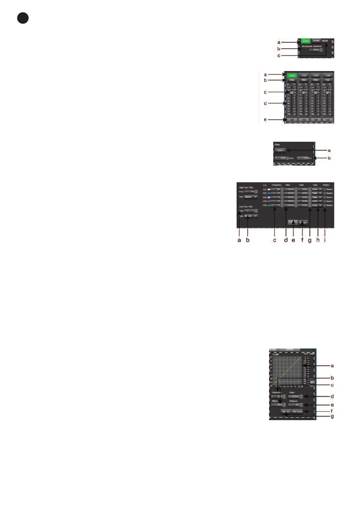
6.- COMPRESSION MODULE
Limits the dynamic of the signal for each input channel. When the signal exceeds
the threshold, it is compressed in a ratio greater than 1. Below the threshold, the
compressor does not modify the signal. By adjusting the ratio to its maximum
value (Limit), the compressor becomes a limiter.
a.- Graphic view of the Compressor module.
b.- Threshold: threshold value, above this value the signal will be compressed
according to the selected compression ratio.
c.- Attack: compressor reaction time when the input signal is above the
threshold level.
d.- Ratio: compression ratio between the input signal and the compressed
signal.
e.- Release: release time of the compressor when the signal is above the
threshold value.
f.- Flat Comp: sets the Compressor module default values .
g.- Bypass: the input signal is not processed and is diverted to the next processing module.
- 12 -
E
N