Foundry Hardware Installation Guide for the FES, FESX, and FWSX
2 - 8 © 2006 Foundry Networks, Inc. June 2006
• Optionally, one or two 10-Gigabit Ethernet uplink ports for 10-Gigabit Small Form Factor Pluggable (XFP)
MSA-compliant optical transceivers
Note that one port out of the first four Copper ports or the four Fiber ports can be active at a time (see “FES 10/
100/1000 Mbps Ports” on page 2-9). For example, you can use ports 1 –4 of the Gigabit Copper ports or ports 1F
– 4F of the Gigabit Fiber ports. You can use a combination of fiber and copper ports or all copper or all fiber ports,
as needed.
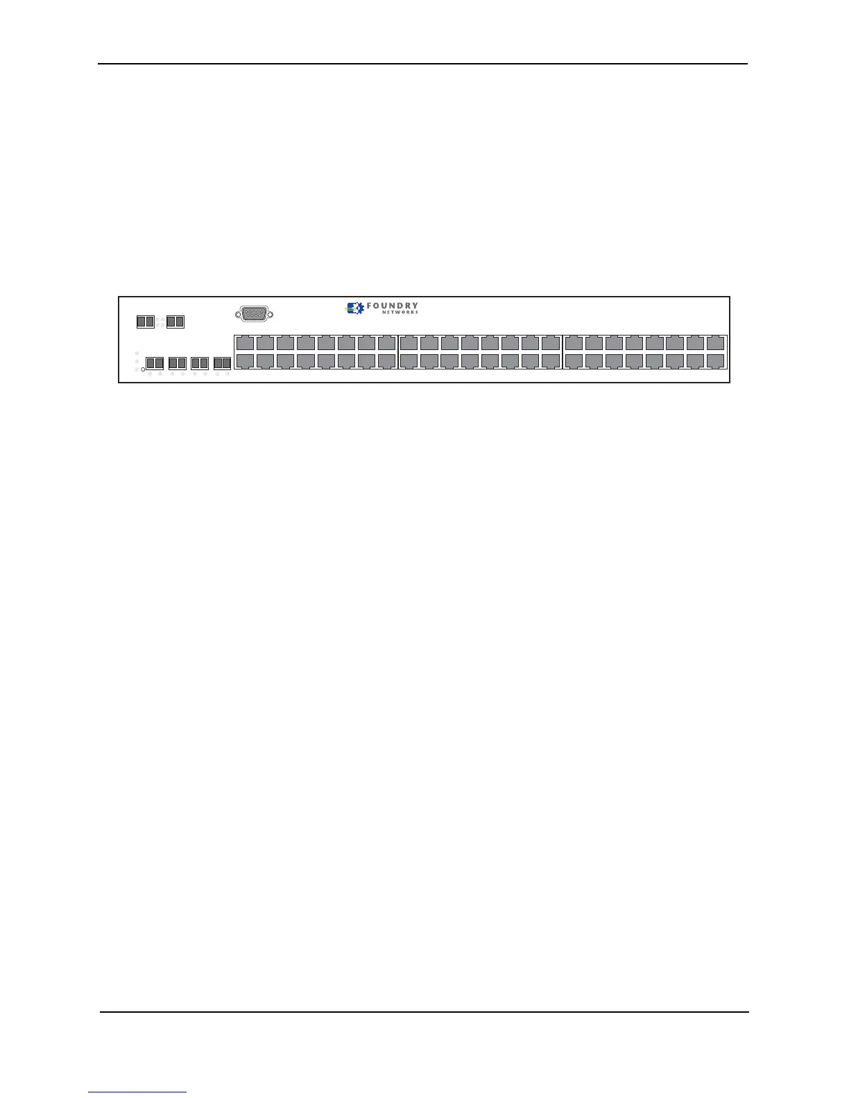
The following figure shows the front panel of the FESX448. The FESX648 and FWSX448 looks similar to the
FESX448.
Figure 2.10 FESX448 Front Panel
Control Features
Each device’s front panel has the following control features:
• Serial management interface (the port labeled Console)
• Reset button
• 10/100 ports with RJ-45 copper connectors (FES only)
• 10/100/1000 ports with RJ-45 copper connectors
• 10/100/1000 ports with mini-GBIC slots for SFP MSA-compliant fiber transceivers
• 100/1000 ports with mini-GBIC slots for SFP MSA-compliant fiber transceivers (FESX424HF)
• Optionally, one or two 10 Gigabit Ethernet ports for XFP MSA-compliant fiber connector(s) (FESX and FWSX
only)
Serial Management Interface (Console Port)
The serial management interface enables you to configure and manage the device using a third-party terminal
emulation application on a directly connected PC. A straight-through EIA/TIA DB-9 serial cable (M/F) ships with
the device. The serial management interface (the port labeled Console) is located in the left corner of the front
panel.
Reset Button
The reset button allows you to restart the system without switching the power supplies off and on or using the CLI
or Web management interface. The button is located to the right of the serial management interface and is
recessed to prevent it from being pushed accidentally.
FES Network Interfaces
The FES2402, 4802, and 9604 provide the following interfaces:
• 10Base-T/100Base-T (10/100) copper ports
• 10/100/1000Base-T copper or Fiber Gigabit uplink ports
The FES12GCF provides the following interfaces:
• 10/100/1000Base-T copper or Fiber Gigabit uplink ports
For information about the type of fiber optic modules supported on FES devices, see “Fiber Optic Modules” on
page 2-15.
Console
PS2
PS1
Power
1
2
FastIron Edge X448
1F
Lnk
Act
Lnk
Act
2F
Lnk
Act
3F
Lnk
Act
4F
Lnk
Act
1
2
3
4
1
2
5
6
1
2
7
8
9
10
11
12
15
16
17
18
19
20
21
22
23
24
Act
Lnk
25/49 26/50
13
14
25
26
31
3230
27
28
29
33
34
35
36
37
38
39
40
41
42
47
4846
43
44
45