Connecting Network Devices and Checking Connectivity
June 2006 © 2006 Foundry Networks, Inc. 4 - 5
Connecting Network Devices
Foundry devices support connections to other vendors’ routers, switches, and hubs, as well other Foundry
devices.
Connectors
• 10Base-T/100Base-TX ports come with RJ-45 jacks for standard unshielded twisted pair (UTP/Category 5)
cable connections.
• 1000Base-T ports come equipped with RJ-45 connectors.
• 1000Base-SX ports come equipped with SC connectors for SFP transceivers.
• 1000Base-LX ports come equipped with SC connectors for SFP transceivers.
• 1000Base-LH ports come equipped with SC connectors for SFP transceivers.
• 10GBase-ER ports come equipped with LC connectors for XFP transceivers.
• 10GBase-LR ports come equipped with LC connectors for XFP transceivers.
• 10GBase-SR ports come equipped with LC connectors for XFP transceivers.
For port pinouts, see the section “10/100 and Gigabit Port Pinouts” on page 7-4.
Cable Specifications
See “Cable Specifications” on page 7-5 for cable lengths and types.
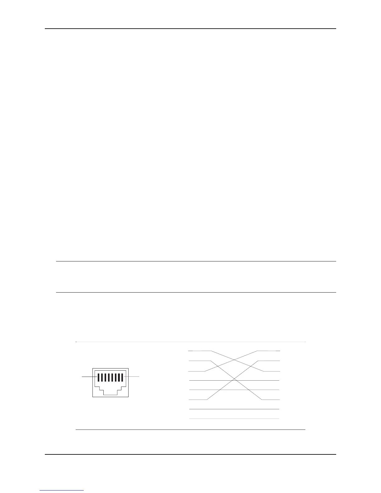
Connecting to Ethernet or Fast Ethernet Hubs
For copper connections to Ethernet hubs, a 10/100BaseTX or 1000BaseT switch, or another Foundry device, a
crossover cable is required (Figure 4.1 and Figure 4.2). If the hub is equipped with an uplink port, it will require a
straight-through cable instead of a crossover cable.
NOTE: The 802.3ab standard (automatic MDI/MDIX detection) calls for automatic negotiation of the connection
between two 1000Base-T ports. Therefore, a crossover cable may not be required; a straight-through cable may
work as well. For more information about this feature, see the Foundry FastIron X-Series Configuration Guide or
the Foundry Switch and Router Installation and Basic Configuration Guide.
Figure 4.1 UTP crossover cable
1
2
3
4
5
6
7
8
1
2
3
4
5
6
7
8
1
8
UTP Crossover Cable
10/100BaseTX
unused
unused
unused
unused
unused
unused
unused
unused