Hardware Specifications
December 2008 © 2008 Foundry Networks, Inc. 7 - 11
NOTE: Cable installation and network configuration will affect overall transmission capability. The numbers
provided above represent the accepted recommendations of the various standards. For network-specific
recommendations, consult your local Foundry reseller or system engineer.
Power Cords
All of the FastIron devices ship with US-compatible power cords unless otherwise specified at the time of order.
United Kingdom- and European-compatible power cords are also available.
See also “Input Connector and Plug” on page 7-14
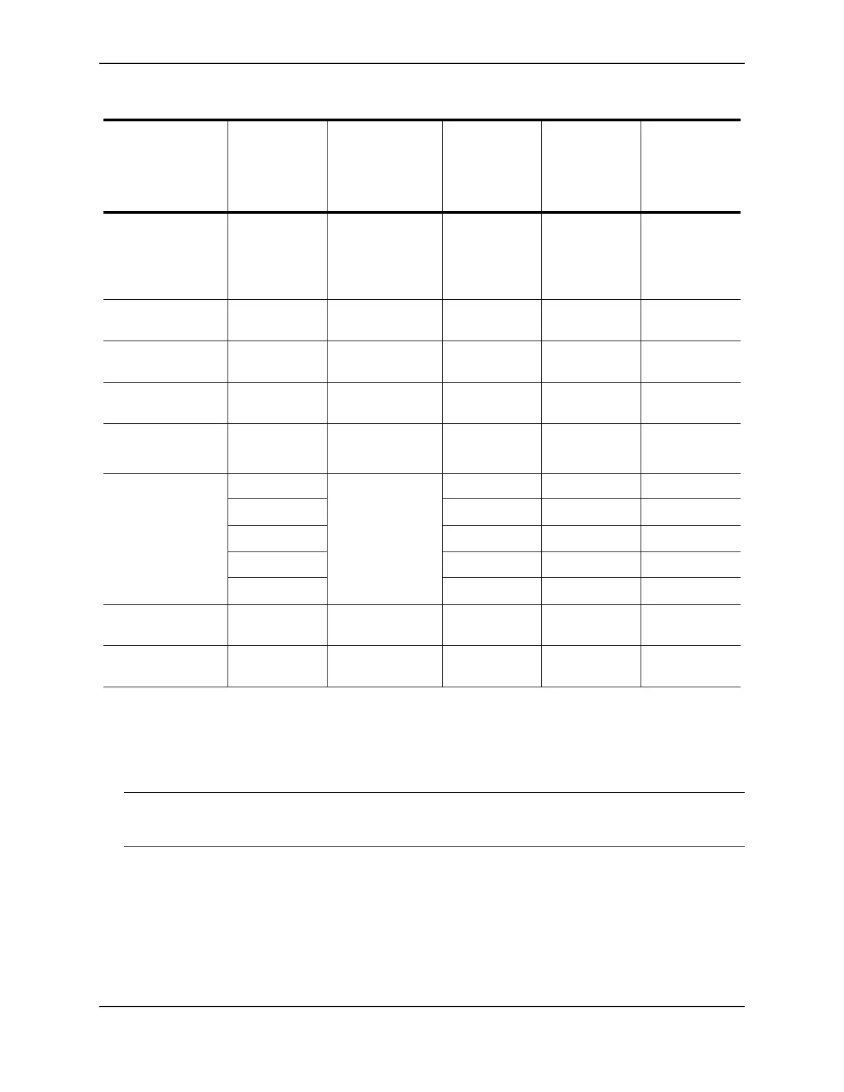
10Base-T/
100Base-TX
Copper RJ-45 jack for
standard
unshielded
twisted pair (UTP/
Category 5)
n/a n/a up to 100
meters
10GBase-1310 MMF LC connector for
XFP module
9 1310 nm up to 200
meters
10GBase-CX4 Copper CX4 connector for
XFP module
n/a n/a up to 15
meters
10GBase-ER SMF LC connector for
XFP module
9 1550 nm up to 40000
(40 km)
10GBase-LR SMF LC connector for
XFP module
9 1310 nm 2 – 10000
(10km)
10GBase-SR MMF LC connector for
XFP module
62.5/125 160 2 – 26
MMF 62.5/125 200 2 – 33
MMF 50/125 400 2 – 66
MMF 50/125 500 2 – 82
MMF 50/125 2000 2 – 300
10GBase-ZR SMF LC connector for
XFP module
9 1550 nm up to 80000
(80 km)
10GBase-ZRD SMF LC connector for
XFP module
9 1530.33 –
1561.42 nm
up to 80000
(80 km)
1. SMF = Single Mode Fiber, MMF = Multi-Mode Fiber
2. The TIA 568 building wiring standard specifies 160/500 MHz*km MMF (Multi-mode Fiber).
3. The international ISO/IEC 11801 building wiring standard specifies 200/500 MHz*km MMF.
4. The ANSI Fibre Channel specification specifies 500/500 MHz*km 50 micron MMF and 500/500 MHz*km
fiber has been proposed for addition to ISO/IEC 11801.
Table 7.6: Cable Specifications (Continued)
Network Interface
Cable Type
1
Connector Type Core
Diameter
(microns)
Modal
Bandwidth
(MHz*km) or
Wavelength
(nm)
Range
(meters)