Replacing and Maintaining the Hardware
December 2008 © 2008 Foundry Networks, Inc. 6 - 9
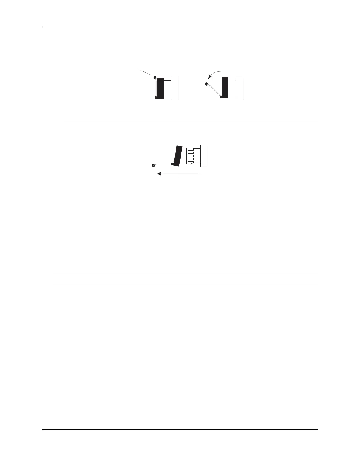
4. Pull the fiber optic module out of the port by pulling the bail latch forward, away from the front panel of the
module. This unlocks the module from the front panel.
NOTE: The bail latch may be attached to either the top or the bottom of the mini-GBIC.
5. Grasping the bail latch, pull the fiber optic module out of the port.
6. Store the fiber optic module in a safe, static-free place or in an anti-static bag.
7. Install a new fiber optic module in the port. For information about performing this task, see “Installing a New
Fiber Optic Module”.
Installing a New Fiber Optic Module
You must install a fiber optic module (SFP or XFP transceiver) in each Gigabit Ethernet and 10-Gigabit Ethernet
fiber port you want to use.
You can install a new fiber optic module in a port while the FastIron Stackable device is powered on and running.
Before installing one of these modules into the port, obtain an ESD wrist strap with a plug for connection to a metal
surface.
WARNING: For safety reasons, the ESD wrist strap should contain a series 1 meg ohm resistor.
To install a fiber optic module, do the following:
1. Put on the ESD wrist strap and ground yourself by attaching the clip end to a metal surface (such as an
equipment rack) to act as ground.
2. Remove the new module from its protective packaging.
3. Gently insert the fiber optic module into the port until the module clicks into place. The module is keyed to
prevent incorrect insertion.
Cabling a Fiber Optic Module
To cable a fiber optic module, do the following:
1. Remove the protective covering from the fiber-optic port connectors and store the covering for future use.
2. Before cabling a fiber optic module, Foundry strongly recommends cleaning the cable connectors and the
port connectors. See “Cleaning the Fiber-Optic Connectors” on page 6-10.
3. Gently insert the cable connector(s) (a tab on each connector should face upward) into the port connector(s)
until the tabs lock into place.
4. Observe the link and active LEDs to determine if the network connections are functioning properly. For more
information about the LED indicators, see Table 4.2 on page 4-11.
Bail Latch
Bail Latch