Chapter 2 Installation Instructions
17
865G/GV/PE7MC User Manual
Reset Switch (RESET)
Attach the connector to the Reset switch on the front panel of the case; the
system will restart when the switch is pressed.
Power LED Connector (PLED)
Attach the connector to the power LED on the front panel of the case. The Power
LED indicates the system’s status. When the system is in S0 status, the LED is
on. When the system is in S1 status, the LED is blink; When the system is in S3,
S4, S5 status, the LED is off.
Power Button Connector (PWRBTN#)
Attach the connector to the power switch of the case. Pushing this switch allows
the system to be turned on and shut down.
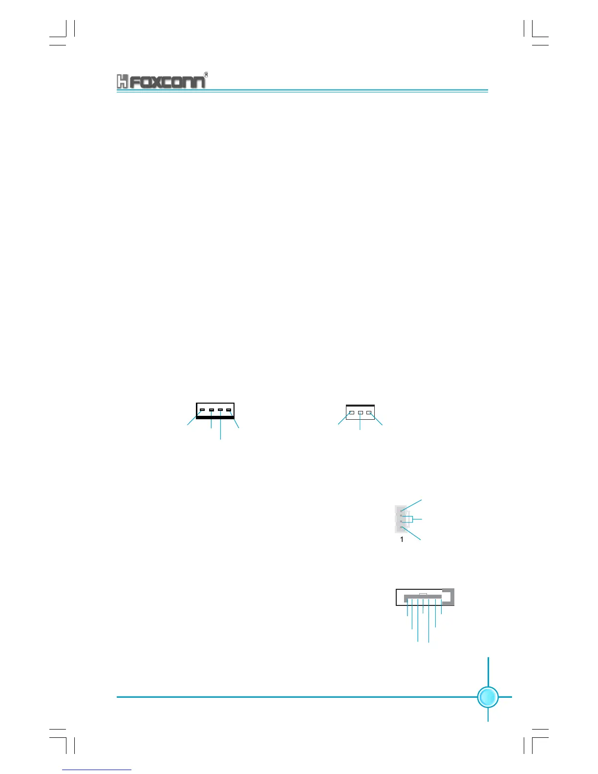
Fan Connectors : CPU_FAN, FAN1
The fan speed of CPU_FAN and FAN1 can be detected and viewed in “PC
Health Status” section of the CMOS Setup. These fans will be automatically
turned off after the system enters S3, S4 and S5 mode.
CD_IN Connector: CD_IN
CD_IN is Sony standard CD audio connectors, it can
be connected to a CD-ROM drive through a CD audio
cable.
S-ATA Connectors: CN20, CN21
The S-ATA header is used to connect the S-ATA device
to the motherboard. These connectors support the thin
Serial ATA cables for primary internal storage devices.
The current Serial ATA interface allows up to 150MB/s
data transfer rate, faster than the standard parallel ATA
with 133MB/s (Ultra ATA/133).
SATA _1/SATA _2
GND
GND GND
RX+
RX-
TX+
TX-
CD_IN
CD_L
GND
CD_R
FAN1
+12V
GND
1
SENSE
POWER
GROUND
CONTROL
SENSE
1
CPU FAN
 Loading...