Page 12
Replace the motor if necessary. Do not lubricate the motor or the gears. To reinstall the motor, move the spring clip loop to the
right and hold. Gently turn the motor while inserting so that the gear on the motor meshes with the gears under the drive gear cover.
Release the spring clip loop and continue to rotate the motor until the motor housing engages the small plastic bulge inside the drive
bracket motor retainer. Reconnect the motor plug to the two-pronged jack on the lower left-hand side of the PC board. If the motor
will not easily engage with the drive gear when reinstalling, lift and slightly rotate the motor before reinserting. Reconnect the
power plug.
Replace the valve cover. After completing any valve maintenance, press and hold NEXT and REGEN buttons for 3 seconds or
unplug power source jack (black wire) and plug back in. This resets the electronics and establishes the service piston position. The
display should flash all wording, then flash the software version and then reset the valve to the service position.
Drive Cap Assembly
Disassembly 1.5" Valves
Turn off supply water and relieve system pressure. The drive assembly must be removed to access the drive cap assembly. The drive
cap assembly must be removed to access the piston(s). The drive cap assembly is threaded into the control valve body and seals with
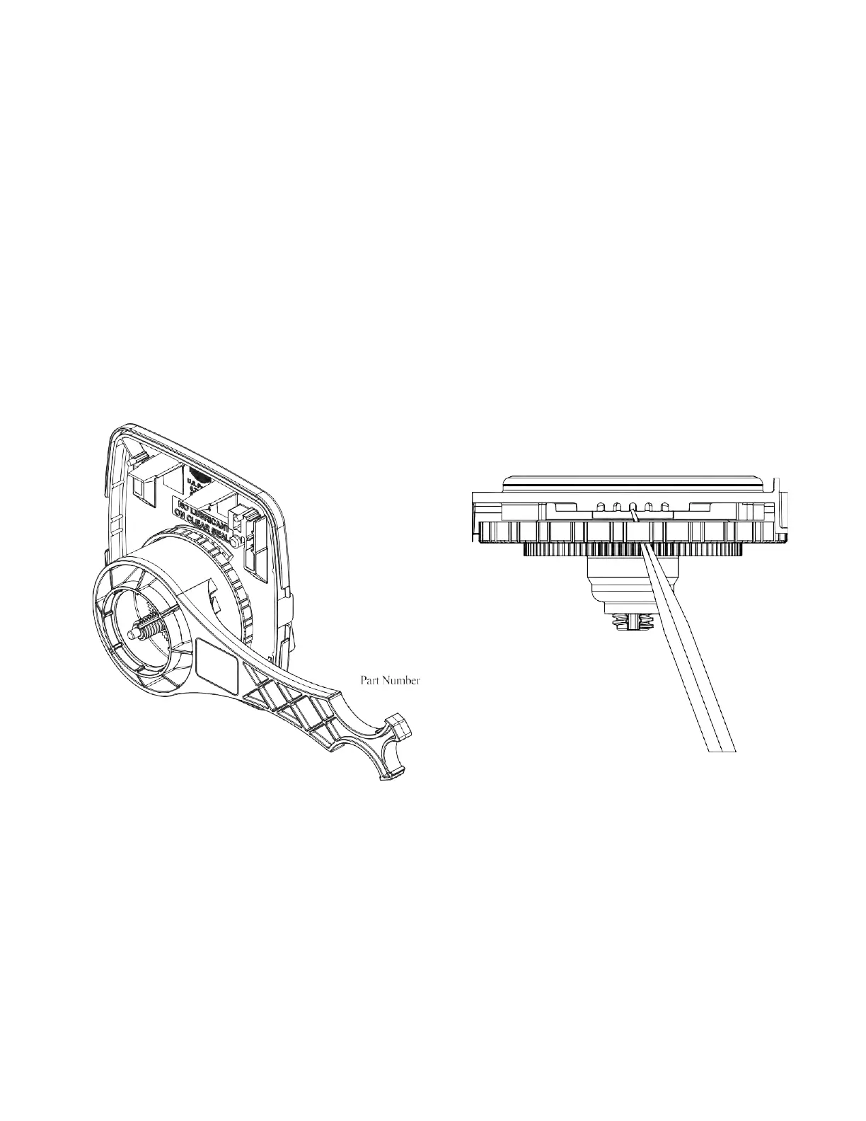
an O-ring. To remove the drive cap assembly, use the special plastic wrench (V3193-02 Figure 1) or insert a ¼” to ½” flat bladed
screwdriver into one of the slots around the top 2” of the drive cap assembly so it engages the notches molded into the drive back
plate around the top 2” of the piston cavity. See Figure 2. The notches are visible through the holes. Lever the screwdriver so the
drive cap assembly turns counterclockwise. Once loosened unscrew the drive cap assembly by hand and pull straight out.
Figure: 1
Figure: 2
Disassembly, 2" Valves
After removing the bracket assembly, the drive back plate can be removed by squeezing the 2 locking tabs (located at 3 and
9 o-clock around the white gear) and rotating the back plate counter clockwise. The four
1
⁄4-20 screws can then be removed and the
drive cap pulled straight back out of the valve. Turning the main gear counter clockwise drives the piston in and may aid in pushing
out the cap.
Inspection
The drive cap assembly contains the drive cap, the main drive gear, drive cap spline, piston rod and various other parts that should
not be dissembled in the field. Visually inspect the drive cap for damage and free operation of the gear and threaded rod. The only
replaceable part on the drive cap assembly is the O-ring.