Page 8
Installation
GENERAL INSTALLATION & SERVICE WARNINGS
The control valve and fittings are not designed to support the
weight of the system or the plumbing.
Do not use Vaseline, oils, other hydrocarbon lubricants, or
spray silicone anywhere. A silicone lubricant may be used on
black O-rings but is not necessary.
HYDROCARBONS SUCH AS KEROSENE, BENZENE,
GASOLINE, ETC., MAY DAMAGE PRODUCTS THAT
CONTAIN O-RINGS OR PLASTIC COMPONENTS. EXPOSURE TO SUCH HYDROCARBONS MAY CAUSE THE
PRODUCTS TO LEAK. DO NOT USE THE PRODUCT(S) CONTAINED IN THIS DOCUMENT ON WATER SUPPLIES
THAT CONTAIN HYDROCARBONS SUCH AS KEROSENE, BENZENE, GASOLINE, ETC.
CLACK WATER METERS SHOULD NOT BE USED AS THE PRIMARY MONITORING DEVICE FOR CRITICAL OR
HEALTH EFFECT APPLICATIONS
Teflon tape is recommended to be used on all threads. Do not use pipe dope, as it may break down the plastics in the control valve.
Allow one foot of clearance to service AM1.5 valves and two feet of clearance to service AM2 and AM2QC valves.
The valve will withstand transportation and storage temperatures of -13 ˚F (-25 ˚C) to 131 ˚F (55 ˚C) and for short periods up to
158 ˚F (70 ˚C). If valve has been exposed to freezing conditions let valve warm up to room temperature before running water
through it. The valve has been packaged to prevent damage from the effects of normal humidity, vibration, and shock.
SITE REQUIREMENTS:
1.
The plug-in Power Adapter is for dry locations only, and should be connected to an uninterrupted outlet installed within 15 feet
(4.57 meters) of the water conditioner. If the Power Adapter cord has not yet been connected to the control valve, remove the
control valve cover and the drive bracket, and thread the Power Adapter cord through the hole in the back plate. Reinstall the
drive bracket. Weave the cord through the hooks on the right-hand side of the drive bracket and connect the end to the four-prong
connector on the printed circuit board. Replace the cover, and plug the Power Adapter into an uninterrupted outlet.
2.
The tanks should be on a firm, level surface.
3.
All plumbing should be done in accordance with local codes.
4.
Do not locate the unit where it or its connections (including the drain and overflow lines) will ever be subjected to room
temperatures below 40° F (4° C).
5.
INLET/OUTLET PLUMBING: Connect to a supply line downstream of outdoor spigots. Install an inlet shutoff valve and plumb
to the unit’s inlet. Installation of a bypass valve is recommended. If using plastic fittings, ground the water conditioner per local
electrical codes. Do not install any water conditioner with less than 10 feet of piping between its outlet and the inlet of a water
heater. If a water meter is used, install the water meter on the outlet side of the control valve. The turbine assembly may be
oriented in any direction but is usually oriented pointing up to reduce drainage out of the pipe during service.
6.
Locate the water conditioner so the distance between the drain and the water conditioner is as short as possible. All units are
shipped without a drain line flow control washer. Correctly size the drain line and install an appropriately sized drain line flow
control. 1.5” valves are shipped with a ¾” fitting that can be used with the drain line flow control up to 10 gpm, or an optional
1” fitting can be purchased to be used with drain line flow controls up to 25 gpm. For higher backwash rates, the adapter can be
removed and the 1 ¼” NPT threaded drain outlet can be used. For 2” valves the drain outlet is 1.5” NPT threads. Solder joints
near the drain must be done before connecting the drain line flow control fitting. Leave at least 6” (152.4mm) between the drain
line flow control fitting and the solder joints to prevent heat from damaging the flow control. Avoid elevating the drain line above
the control valve where possible. Discharge the drain line through an air gap to a receptacle in accordance with local plumbing
codes.
IMPORTANT: Never insert a drain line directly into a drain, sewer line, or trap. Always allow an air gap between the drain line
and the receptacle to prevent back siphonage.
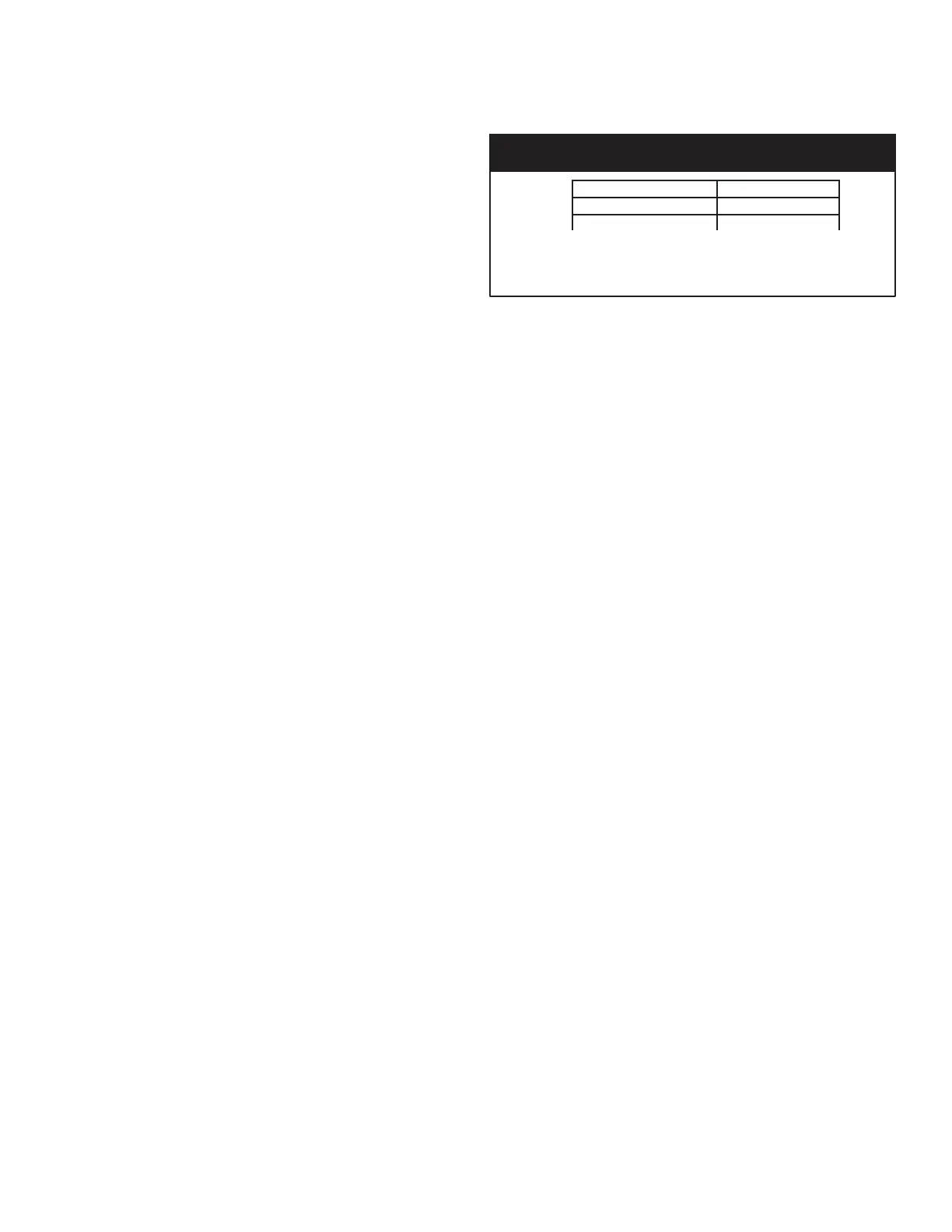
A = Number of inches above the top of the tank for fiberglass tanks.
Please verify distributor pipe and pilot O-ring engagement. Installer
must determine engagement to be able to allow for tank expansion.
Distributor Tube Pipe Height
for Top Mount AM1.5, AMS2 and AM2 QC control valves
2
4
2