Page 35
B indicates BSPT
N indicates NPT
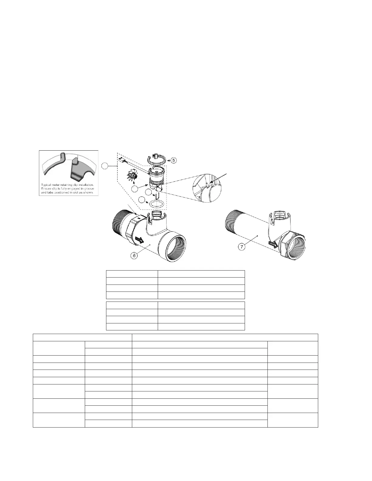
Meter Assembly for AM1.5 and AM2 Valves
Note: Be sure the proper meter size is programmed in the software.
Standard meter cable is used for spacing up to 3” between the valve body and meter body, longer distance requires longer cable #V3221.
Service or replace the turbine by:
1.
Turn the bypass for the system on and relieve the pressure on the system before removing the meter.
2.
Press downward on the remote meter assembly to relieve tension on the retaining clip V3632. Remove the clip and take the meter
assembly out of the housing.
3.
Remove the bend from the two exposed tips of the retaining clip V3501 and remove the clip.
4.
Service or replace the V3118-03 AM15/2 Turbine Assembly and place it back on the turbine shaft.
5.
Insert the V3501 AM15/2 Turbine Clip and re-bend the exposed ends of the clip. The V3118-03 turbine has a groove to line up
with the V3501 AM15/2 Turbine Clip.
6.
Insert meter assembly back into the meter housing.
7.
Re-install the meter retaining clip V3632 as shown below.
8.
Open the bypass for the system slowly to bring it back into service and check to be sure you have no water
leaks. The V3118-03 has a groove to line up with the V3501 AM1.5/2 Turbine Clip.
1.5” NPT Meter, 28” Cable
1.5” BSPT Meter, 28” Cable
1.5” NPT Meter, 15’ Cable
1.5” BSPT Meter, 15’ Cable
1
Commercial meter assembly, 28” Cable
1
Commercial meter assembly, 15’ Cable
Commercial meter turbine assembly
6
1
7
1
1
Installation of the AM2 Meter NPT Assembly can be accomplished with a 2” NPT pipe. For AM2 Meter BSPT Assembly use 63mm pipe.
WHEN INSTALLING THE METER, MAKE SURE THE ARROW ON THE METER BODY IS GOING THE SAME DIRECTION AS THE WATER
FLOW. THIS WATER METER SHOULD NOT BE USED AS THE PRIMARY MONITORING DEVICE FOR CRITICAL OR HEALTH EFFECT
APPLICATIONS. OPERATING PRESSURES: 20 PSI MINIMUM / 125 PSI MAXIMUM • OPERATING TEMPERATURES: 40°F MINIMUM / 110°F
MAXIMUM
The meter can be installed in either horizontal or "upflow" vertical applications
.