Page 36
No Hard Water Bypass:
The MAV will be driven closed before the first regeneration cycle that is
FILL or SOFTENING or FILTERING, and be driven open after the last
regeneration cycle that is not FILL. If the
control valve enters into an error
state during regeneration mode, the MAV will remain in its current state
until the error is corrected and reset.
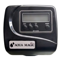
Hard Water Bypass installation prevents water from entering the
plumbing. If a downstream plumbing device or local
requires an uninterrupted water supply, design the installations
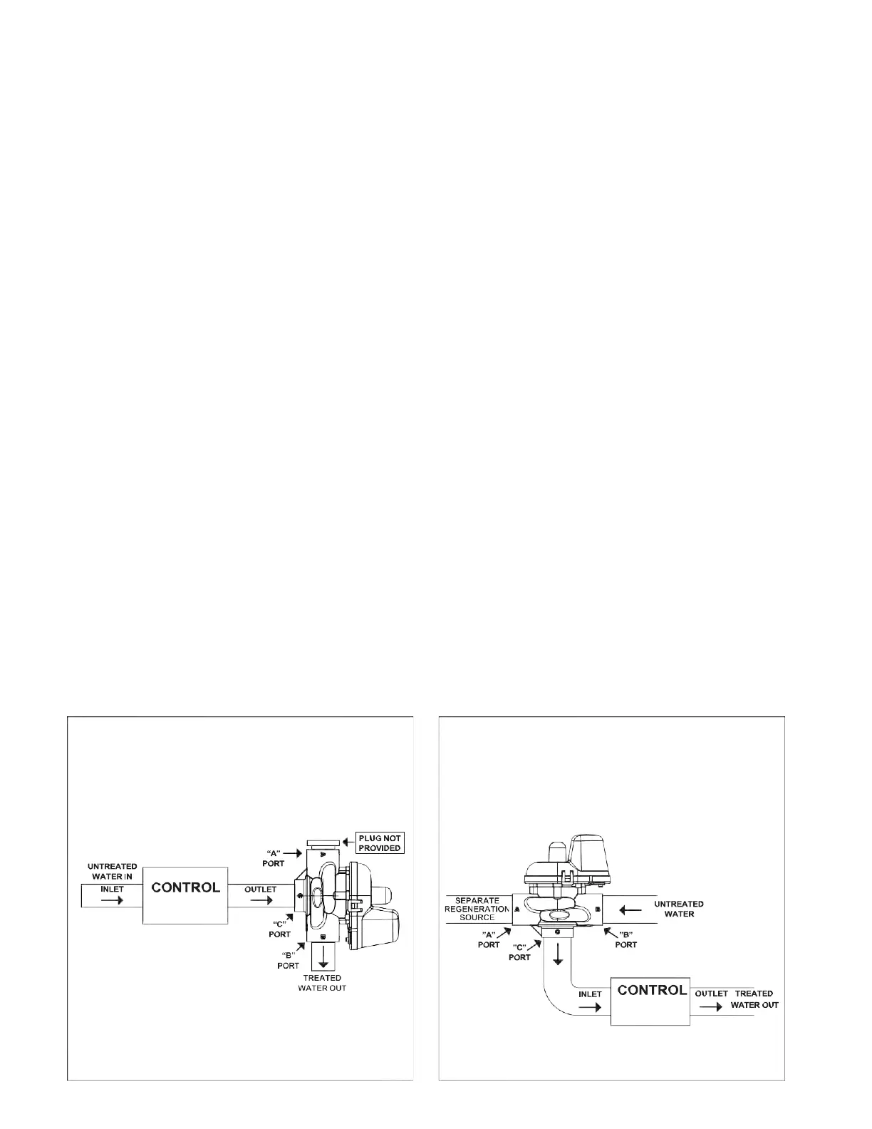
Separate Source Regeneration:
The MAV
will be driven closed (i.e. let water flow from A port to C port)
the first regeneration cycle, and be driven open (i.e. let water flow
B port to C port) after the last regeneration cycle. If the control valve
during regeneration mode, the MAV will remain in its
current state until the error is corrected and reset.
there is a treated water demand during regeneration, separate
source water will be used.
Motorized Alternating Valve Piston Style Applications
For V3071, V3071BSPT, V3076 or V3076BSPT
OPERATING PRESSURES: 20 PSI MINIMUM / 125 PSI MAXIMUM
OPERATING TEMPERATURES: 40°F MINIMUM / 110°F MAXIMUM
Service or Installation of Motor: Do not lubricate the motor or the gears. To install the motor, move the spring clip loop to the right and
hold. Gently turn the motor while inserting it so that the gear on the motor meshes with the gears under the drive gear cover. If the motor
will not easily engage with the drive gears when reinstalling, lift and slightly rotate the motor before reinserting. Release the spring clip
loop and continue to rotate the motor until the wires are horizontal and the motor housing engages the small plastic bulge inside the drive
bracket motor retainer. Reconnect the motor plug to the two-pronged jack on the board labeled drive.
If the control valve manual does not include instructions for setting up the software for No Hard Water Bypasses (NHWB), Separate
Source (SEPS), or Twin Tank Operation (ALT A and ALT b), please contact your local equipment supplier for current copies of installation
instructions.
Up to 2 additional cables can be brought through the back plate. Locate the round strain relief knock-out on the inside of the back plate.
Use a punch and hammer to remove the knock-out. One or both tabs at the bottom of the strain relief feature may be broken out with
needle-nose pliers. The additional cables may be brought through the knock-out hole, and connected to the PC board. After the cables
are connected to the PC board, weave the cables through the strain relief feature, and then use V3805 Strain Relief Cover Kit to cover the
cables in the strain relief. To help prevent damage to the cables, allow nearby solder joints to cool, or solvent cement joints to cure.
•
For twin tank operation, the 8’ interconnect cable must be threaded through the back plates and connected to the three-pin
connector labeled COMM CABLE on both the ALT A and ALT b control valves. The 8’ interconnect cable is not used for No
Hard Water Bypass (NHWB) or Separate Source (SEPS) operation. NOTE: It is possible to use the Motorized Alternating Valve
on controls with individual meters with some International or Custom PC Boards. When using the Motorized Alternating Valve
with two meters, it is necessary to disconnect or cut the left wire on the interconnect cable. This is the wire closest to the center
cut out on the PC Board.
•
The 8’ alternator valve motor cable must be threaded through the back plate and connected to the two-pin connector labeled MAV
on the control valve board (for twin tank operation connect to the unit set as ALT A).
•
The 15’ water meter cable must be threaded through the back plate and connected to the three-pin connection labeled METER
on the control valve board. NOTE: A meter must be used for twin tank operation, meters are recommended but not required for
NHWB or SEPS operation. If using the Motorized Alternating Valve with a meter on each control, it is necessary to connect each
meter to the PC Board.
•
The 15’ AC Adapter or power cable must be threaded through the back plate of all control valves. The AC adapter should
be installed to a properly grounded (not switched) outlet.