070.610-IOM (JUL 21)
Page 12
RWF II Rotary Screw Compressor Units
Installation
Due to the tendency of the port pressure to fall with de-
creasing compressor capacity, a back-pressure regulator
valve (BPR) is generally required on a ash economizer sys-
tem (see Figure 15) in order to maintain some preset pres-
sure dif ference between the subcooled liquid in the ash
vessel and the evaporato rs. If the back-pressure regula-
tor valve is not used on a ash economizer, it is possible
that no pressure difference will exist to drive liquid from
the ash vessel to the evaporators, since the ash vessel
pressure will approach suction pressure at a decreased
slide valve position. In cases where wide swings in pres-
sure are anticipated in the ash econo mizer vessel, it may
be necessary to add an outlet pressure regulator to the
ash vessel outlet to avoid overpressurizing the econo-
mizer port, which could result in motor overload. Example:
A system feeding liquid to the ash vessel in batches.
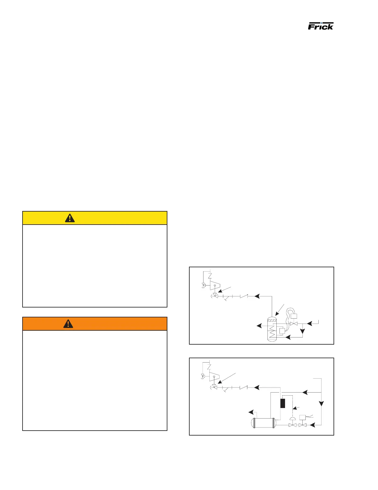
The recommended economizer systems are shown in Fig-
ure 13 to Figure 16. Notice that in all systems there should
be a strainer (STR) and a check valve (VCK) between the
economizer vessel and the economizer port on the com-
pressor. The strainer prevents dirt from passing into the
compressor and the check valve prevents oil from owing
from the compressor unit to the econo mizer vessel during
shutdown.
CAUTION
Other than the isolation valve needed for strainer
cleaning, it is essential that the strainer be the last
device in the economizer line before the compres sor.
The strainer must be strong enough to handle the gas
pulsations from the compressor. Johnson Controls-
Frick recommends an R/S or Hansen strainer. Also,
piston-type check valves are recom mended for instal-
lation in the economizer line, as opposed to disc-type
check valves. The latter are more prone to gas-pul-
sation-induced failure. The isolation and check valves
and strainer should be located as closely as possible
to the compressor, preferably within a few feet.
WARNING
Heat generated from compression could result in a
re, serious injury or property damage.
Recompression of gas between the compressor side/
economizer port and a check valve may occur during
low or no ow situations. This is common when an
isolation or solenoid valve is closed upstream of the
compressor port. Excessive heat will occur in this
piping section.
Minimize the length of affected piping by installing a
check valve as close to the side/economizer port as
possible. If this section of piping requires insulation,
then only high temperature insulation shall be used.
Trained technicians are required for servicing.
For refrigeration plants employing multiple compressors on
a common economizing vessel, regardless of economizer
type, each compressor must have a back-pressure regulat-
ing valve in order to balance the economizer load, or gas
ow, between compressors. The problem of balancing load
becomes most important when one or more compressors
run at partial load, exposing the economizer port to suction
pressure. In the case of a ash vessel, there is no need for
the redundancy of a back-pressure regulating valve on the
vessel and each of the multiple compressors. Omit the BPR
valve on the ash economizer vessel and use one on each
compressor, as shown in Figure 16. It is also recommended
that the back-pressure regulating valves, used on econo-
mizer lines, should be specied with electric shutoff option.
The electric shutoff feature is necessary to prevent ow
from the common economizer vessel to the suction side
of a stopped compressor, through the suction check valve
bypass line, if the other compressors and the common
economizer vessel are still operating and the HV2 valve on
the suction bypass is open.
For refrigeration plants using a Packaged Refrigerant
Recirculation Unit and a direct expansion (DX) economizer
system it is necessary to operate the liquid feed solenoid
on the unit and the liquid feed solenoid on the DX vessel
off of a common signal to avoid liquid overfeed on the DX
economizer system.
If multiple compressors are operated with a common
economizer vessel, it is necessary to install a back-pres-
sure regulator valve with an electric shutoff option in the
vapor line piped to the compressor's economizer port.
Figure 13: Shell and coil economizer system
HIGH
PRESSURE
LIQUID
INTERMEDIATE PRESSURE
GASTO COMPRESSOR
SUCTION
STR
VCK
SUBCOOLED
HIGH PRESSURE
LIQUID TO
EVAPORATOR
ECONOMIZER
COOLER
ECON1
HV-2
Figure 14: Direct expansion economizer system
HIGH
PRESSURE
LIQUID
INTERMEDIATE PRESSURE
GASTO COMPRESSOR
SUCTION
STR
VCK
SUBCOOLED
HIGH PRESSURE
LIQUID TO
EVAPORATOR
ECONOMIZER
COOLER
WIRING
ECON2
HV-2

 Loading...