070.650-IOM (AUG 2015)
Page 16
SGC ROTARY SCREW COMPRESSOR
INSTALLATION
Thebestinsuranceforatrouble-freeinstallationistormly
anchor the compressor to a suitable foundation using
proper bolting and by preventing piping stress from being
imposed on the compressor. Once the compressor is rigged
into place, its feet must be shimmed to level it. There must
be absolutely no stresses introduced into the compressor
bodyduetoboltingofthefeetandanges.
The compressor motor mount is not designed to carry the
unsupported weight of the motor. The full motor weight
must be supported using the motor lifting point during the
motor installation process. After the necessary bracket to
support the motor have been welded into place on the
package and the rear motor feet and the motor mount have
been bolted into place, the weight of the motor can rest on
the support bracket and the motor mount.
In any screw compressor installation, suction and discharge
lines should be supported in pipe hangers (preferably within
2 feet of vertical pipe run) so that the lines won’t move if
disconnected from the compressor. See table for Allowable
Flange Loads.
Table 3. Allowable Flange Loads
ALLOWABLE FLANGE LOADS
NOZ. MOMENTS (ft-lbf) LOAD (lbf)
SIZE AXIAL VERT. LAT. AXIAL VERT. LAT.
NPS M
R
M
C
M
L
P V
C
V
L
1 25 25 25 50 50 50
1.25 25 25 25 50 50 50
1.5 50 40 40 100 75 75
2 100 70 70 150 125 125
3 250 175 175 225 250 250
4 400 200 200 300 400 400
5 425 400 400 400 450 450
6 1,000 750 750 650 650 650
8 1,500 1,000 1,000 1,500 900 900
10 1,500 1,200 1,200 1,500 1,200 1,200
14 2,000 1,800 1,800 1,700 2,000 2,000
CUSTOMER CONNECTIONS
Asaminimumyoumustconnecttothelocationsspecied
on the port location and oil hydraulic schematic, in addition
to suction and discharge.
Other connections are available for instrumentation, oil
return, and service as noted on the Dimensional Outline
drawing. The electrical connections for the slide stop and
the slide valve transmitters and the solenoid valve coils
must be connected to your control system.
OIL SYSTEM REQUIREMENTS
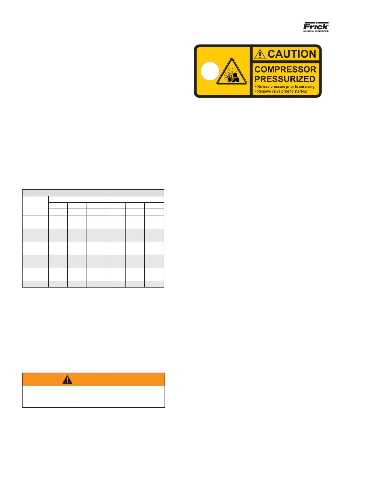
WARNING
Access valves in brass material must be removed and
the holes lled with steel plugs when package is as-
sembled.
Figure 13. Caution/Identication Tag on Access Valve
The oil system must provide oil to the compressor within
limitation on:
• Oil selection
• Oil pressure
• Oil temperature
• Oil cleanliness
OIL SELECTION
The oil selected must be suitable for the application,
refrigerant and operation condition. Compressor bearings
require a minimum viscosity based on size and speed (rpm).
A maximum viscosity of 100 cSt should not be exited.
Frick compressor oils are recommended — see form
160.802-SPC. Also, Coolware provides Frick oil properties
and information on viscosity requirements for a given
compressor selection.
OIL PRESSURE
Design the complete oil system so that the pressure drops
nomorethan15psiwithacleanoillterelement.Thisis
critical for the proper function of the balance piston and to
ensure the life of the axial bearings. For low pressure and
low pressure differential operation, an oil pump must be
built-intoprovidesufcientoilpressure.
The control system needs to be able to check the oil pressure
and compare to both suction and discharge pressures. In
general, oil pressure shall be minimum (1.5 times the suction
pressure +15 psi) and higher than (discharge pressure – 25
psi). For applications with economizer and/or sideloading,
the oil pressure shall additionally be more than 15psi above
the pressure at the side port when in operation.
Advanced control systems like the Frick Quantum HD will
monitor the oil pressure in many more ways in order to
keep the compressor running beyond these basic limits.
This advanced control will keep the compressor running
safely in partial load conditions.
See “Oil Pump” section on page 6 for additional information.
BALANCE PISTON OIL REQUIREMENTS & REGULATIONS
All SG compressors have a balance piston on the male rotor
inlet end (Fig 14). Oil is fed to the balance piston to coun-
teract a portion of the force of gas pressure.
For models using 193-283mm rotors, the balance piston oil
feed is internal using the common oil connection through
theSB-3port(standardconguration).Aseparatecongu-
ration is available for high pressure operation. On 355 and
408 compressors the oil is fed separately through the SB-2
port (Fig 15). The oil pressure must be kept within the spec-
iedrangeonallcompressors.
 Loading...