070.650-IOM (AUG 2015)
Page 6
SGC ROTARY SCREW COMPRESSOR
INSTALLATION - OPERATION - MAINTENANCE
OIL PUMP
A demand oil pump is required for low differential pressure
applications (CoolWare™ will provide a warning when the
oil differential pressure is too low). Oil being supplied to
the compressor from the oil separator is at system
discharge pressure. Within the compressor, oil porting to
all parts of the compressor is vented back to a location in
the compressor’s body that is at a pressure lower than
compressor discharge pressure. All oil entering the
compressor is moved by the compressor rotors out the
compressor outlet and back to the system oil separator.
All SGX compressors are equipped with Squeeze Film
Dampers (SFD) in the rotor blocking diameters. Depending
on operating conditions and power consumption, a full
time and full lube oil pump is required to supply oil to the
compressor (SB-3 & SB-4 ports) at a pressure up to 40-50
psi above discharge pressure. Coolware will provide the
exact calculation at the actual operating condition. If the
calulation information is not available, the oil pressure
should be a minimum of 40 psi above discharge pressure.
On all SG
*
H compressors, the oil pressure to the balance
piston must be controlled and regulated through the SB-2
compressor port. For booster and low pressure applications,
SB-2 may not need to be connected. For higher operating
pressure a Balance Piston Regulator (BPR) must be installed
and piped to the SB-2 connection.
Since there are several variants of the BPR, use Coolware
to select the best option. Correct BPR information and
pressure settings are required. Do not run the compressor
without this information.
NOTICE
DO NOT RUN THE COMPRESSOR WITHOUT
THE CORRECT BALANCE PISTON REGULATOR
INFORMATION AND PRESSURE SETTINGS.
CONSTRUCTION DETAILS
HOUSING: Castings for SGC/SGX screw compressors
through model 3524 are close grain, pressure tight, grey
cast iron to ensure structural integrity and mechanical and
thermal stability under all operating conditions. Ductile
iron housings are also available for special applications.
Standard casing material for SGX 4013-4021 compressor
models is ductile iron grade 60-40-18 per ASTM A395 and
ASME SA395. Contact Johnson Controls – Frick Sales for
additional information.
ROTORS: The rotors are made from the highest quality
steel bar-stock or forgings to the exacting tolerances of
Frick-designed high-efciency rotor proles. The four-
lobed male rotor (5 lobes on 408) is directly connected to
the driver. The six-lobed female rotor (7 lobes on 408) is
drivenbythemaleonathinoillm.
BEARINGS: Antifriction bearings with L
10
rated life in
excess of 50,000 hours at design conditions (using the
Frick Superlter
™
) are used for reduced frictional
horsepower and superior rotor positioning, resulting in
reduced power consumption, particularly at higher
pressure ratios. Cylindrical roller bearings are provided to
handle the radial loads and the thrust loads are absorbed
by four point contact or angular contact bearings. In
addition, thrust balance pistons are provided to reduce the
thrust load and improve bearing life.
SHAFT SEAL: The compressor shaft seal is a single-face
type with a spring-loaded carbon stationary surface riding
against a cast iron rotating seat. The seal is capable of
withstanding static pressure up to 600 psig. During opera-
tion it’s vented to low pressure to provide extended life.
The 408 compressors utilize silicon-tungsten carbide seal
face material.
VOLUMIZER VARIABLE VOLUME RATIO CONTROL: The
Frick compressor includes a method of varying the internal
volume ratio to match the system pressure ratio. Control of
the internal volume ratio eliminates the power penalty
associated with over- or under-compression. Volume ratio
control is achieved by the use of a slide stop which is a
movable portion of the rotor housing that moves axially with
the rotors to control discharge port location. The slide stop
is moved by hydraulic actuation of a control piston. The
range of adjustment is listed in the COMPRESSOR VOLUME
and CAPACITY RATIO table.
STEPLESS CAPACITY CONTROL: Capacity control is
achieved by use of a movable slide valve. The slide valve
moves axially under the rotors to provide fully modulated
capacity control from 100% to minimum load capacity.
Minimum load capacity varies slightly with compressor
model, pressure ratio, discharge pressure level, and rotor
speed. See the TABLE 1 for minimum capacity for all SGC
models.
The slide valve is positioned by hydraulic movement of its
control piston. When in the unloaded position, gas is
bypassed back to suction through a recirculation slot before
compression begins and any work is expended, providing
themostefcientunloading method available for part-load
operation of a screw compressor.
MOTOR MOUNT: SGC/SGX models through 3524 are
designedwithadriveendangethatmateswithacastiron
motor mount (available as a sales order option). The motor
mount is precision machined so that it ensures proper
alignment of the compressor and motor coupling.
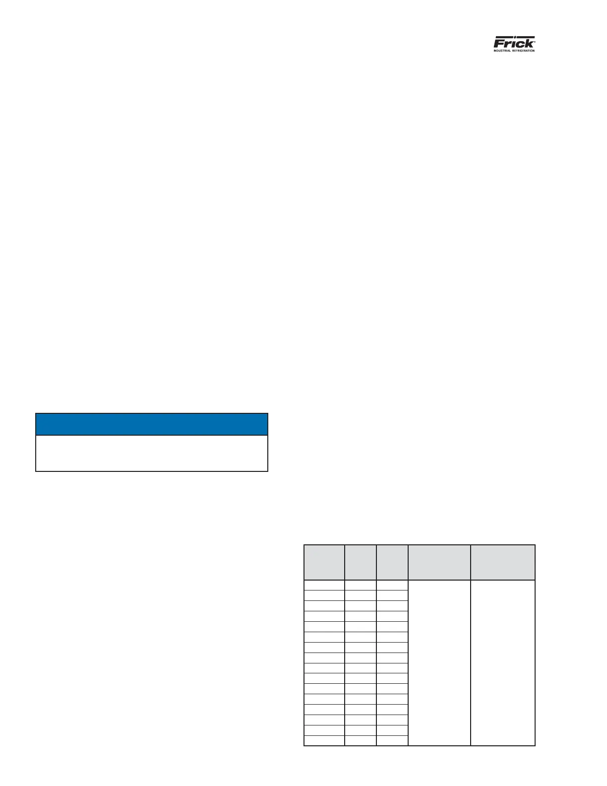
Table 2. COMPRESSOR VOLUME and CAPACITY RATIO
SGC
MODEL
MIN.
VI
(1)
MAX.
VI
MIN.
CAPACITY %
SLIDE VALVE
& SLIDE STOP
TRAVEL
1913 2.2 5.0
REFER TO
COOLWARE
™
REFER TO
NS-7-11
COMPRESSOR
VOLUME
RATIO
AND CAPACITY
INFORMATION
1918 2.2 5.0
2313 2.2 5.0
2317 2.2 5.0
2321 2.2 5.0
2813 2.2 5.0
2817 2.2 5.0
2821 2.2 5.0
2824 2.0 4.1
3511 2.2 5.0
3515 2.2 5.0
3519 2.2 5.0
3524 2.4 4.5
4013 2.2 5.0
4018 2.2 5.0
4021 2.2 4.3
1. Optional 1.7 - 3.0 VI
 Loading...