070.650-IOM (AUG 2015)
Page 21
SGC ROTARY SCREW COMPRESSOR
OPERATION
A
P
DIRECTION
CONTROL VALV E
SV-2
Valve 1
Valve 1
Valve 2
Valve 2
P
T
SC2
1
P
T
A
B
2
SC1
SC1
1
1
BP
1
2
SC2
2
2
SC3
SC3
SCREW IN FLOW
REGULATING
NEEDLE VALVE
SV-3
1
T
B
SC4
2
SC4
DIRECTION
CONTROL
VALVE
HYDRAULIC SCHEMATIC
SGC 1913 – 2824
P
T
YY4 (DECREASE VI)
YY2 (LOAD)
(INCREASE VI) YY3
(UNLOAD) YY1
SC4
BP
SC2
SC3
SC1
YY1
YY2
YY3
YY4
SC3
2
SC4
SC3
1
2
SC2
SC1
2
SC2
1
1
2
A
B
1
P
T
BP
B
A
T
P
SC1
SV-3
T
HYDRAULIC SCHEMATIC
SGC 3511 – 3524
P
SV-2
SCREW IN FLOW
REGULATING
NEEDLE VALVE
SC 4 NOT USED
DIRECTION
CONTROL VALV E
SC-5
SP-1
YY2 (LOAD)
YY4 (DECREASE VI)
COMPRESSOR TOP VIEW
COMPRESSOR TOP VIEW
YY1
YY2
YY3
YY4
(UNLOAD) YY1
(INCREASE VI) YY3
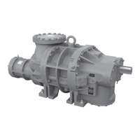
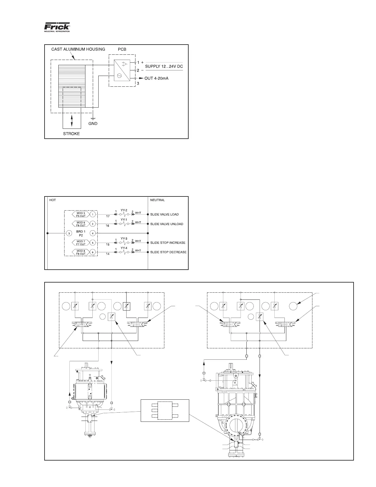
Figure 21. Wiring Diagram for Slide Valve Transmitter
DIRECTIONAL CONTROL VALVES
Solenoids YY1, YY2, YY3 and YY4 must be wired to give
the correct function. A description of their function is given
in the OPERATION chapter. For control system information
refer to Frick Compressor Control Panel 090.040-O. See
wiring diagram in Figure 22.
Figure 22. Directional Control Valve Wiring Diagram
COMPRESSOR HYDRAULIC SYSTEM
(The solenoid valves and manifold block are available as
a sales order option - See Figures 23 and 24)
The compressor hydraulic system actuates the movable slide
valve (SV) to load and unload the compressor. It also actuates
the movable slide stop (SS) to increase or decrease the
compressor’s volume ratio (Vi). The hydraulic cylinder located
at the inlet end of the SGC compressor serves a dual purpose.
Itisseparatedbyaxedbulkheadintotwosections.TheSV
section is to the left of the bulkhead and the SS is to the right
if you are facing the right side of the compressor. Both
operations are controlled by double-acting, four-way solenoid
valves, which are actuated when a signal from the appropriate
microprocessor output energizes the solenoid valve.
SINGLE-ACTING MODE - (> 150 PSI pressure differential)
Open valve at SC1
Close valve at SC2
Open valve at BP (bypass)
Compressor Loading (Single-acting): The compressor
loadswhenSVsolenoidYY2isenergizedandoilowsfrom
the unload side of the cylinder out port SC1, through valve
ports A and T to compressor suction. Simultaneously,
discharge pressure loads the slide valve.
Compressor Unloading (Single-acting): The compressor
unloadswhenSVsolenoidYY1isenergizedandoilows
from the oil manifold through valve ports P and A to cylinder
port SC1 and enters the unload side of the cylinder.
Simultaneously, gas on the load side of the cylinder is
vented through port SC2 and valve BP to compressor
suction.
Figure 23. Hydraulic Schematic
 Loading...