070.250-IOM1 (NOV 2013)
Page 13
TDS_ Rotary Screw Compressor
Installation
The best insurance for a trouble-free installation is to
rmlyanchorthecompressortoasuitablefoundation
using proper bolting and by preventing piping stress from
being imposed on the compressor. Once the compressor
is rigged into place, its feet must be shimmed to level it.
There must be absolutely no stresses introduced into the
compressorbodyduetoboltingofthefeetandanges.
In any screw compressor installation, suction and dis-
charge lines should be supported in pipe hangers (pref-
erably within 2 ft of vertical pipe run) so that the lines
won’t move if disconnected from the compressor. See the
following table for allowableangeloads.
Table 4: Allowable ange loads
Noz.
size
NPS
Moments (ft-lbf) Load (lbf)
Axial Vert. Lat. Axial Vert. Lat.
M
R
M
C
M
L
P V
C
V
L
1 25 25 25 50 50 50
1.25 25 25 25 50 50 50
1.5 50 40 40 100 75 75
2 100 70 70 150 125 125
3 250 175 175 225 250 250
4 400 200 200 300 400 400
5 425 400 400 400 450 450
6 1,000 750 750 650 650 650
8 1,500 1,000 1,000 1,500 900 900
10 1,500 1,200 1,200 1,500 1,200 1,200
14 2,000 1,800 1,800 1,700 2,000 2,000
Customer connections
As a minimum you must connect to the following locations
in addition to suction and discharge.
SB-2 Inlet Bearings and Balance Piston
SB-3 Compressor oil supply
SM-1 Main oil injection
SC-1 Slide Valve Unload Port
SC-2 Slide Valve Load Port
SC-3 Volume Ratio Increase Port
SC-4 Volume Ratio Decrease Port
SD-1 Coalescer Bleed
Other connections are available for instrumentation and
service as noted on the Dimensional Outline drawing. The
electrical connections for the slide stop and the slide valve
transmitters and the solenoid valve coils must be connected
to your control system.
The oil supply system for the compressor must be de-
signed for a total pressure drop of no more than 15 psi
withanewoillterelement.Thisiscriticalfortheproper
operation of the balance piston which is used to ensure
the life of the male axial bearing. Excessive pressure drop
in the oil circuit can also prevent proper operation of the
slide valve and slide stop pistons.
Oil system requirements
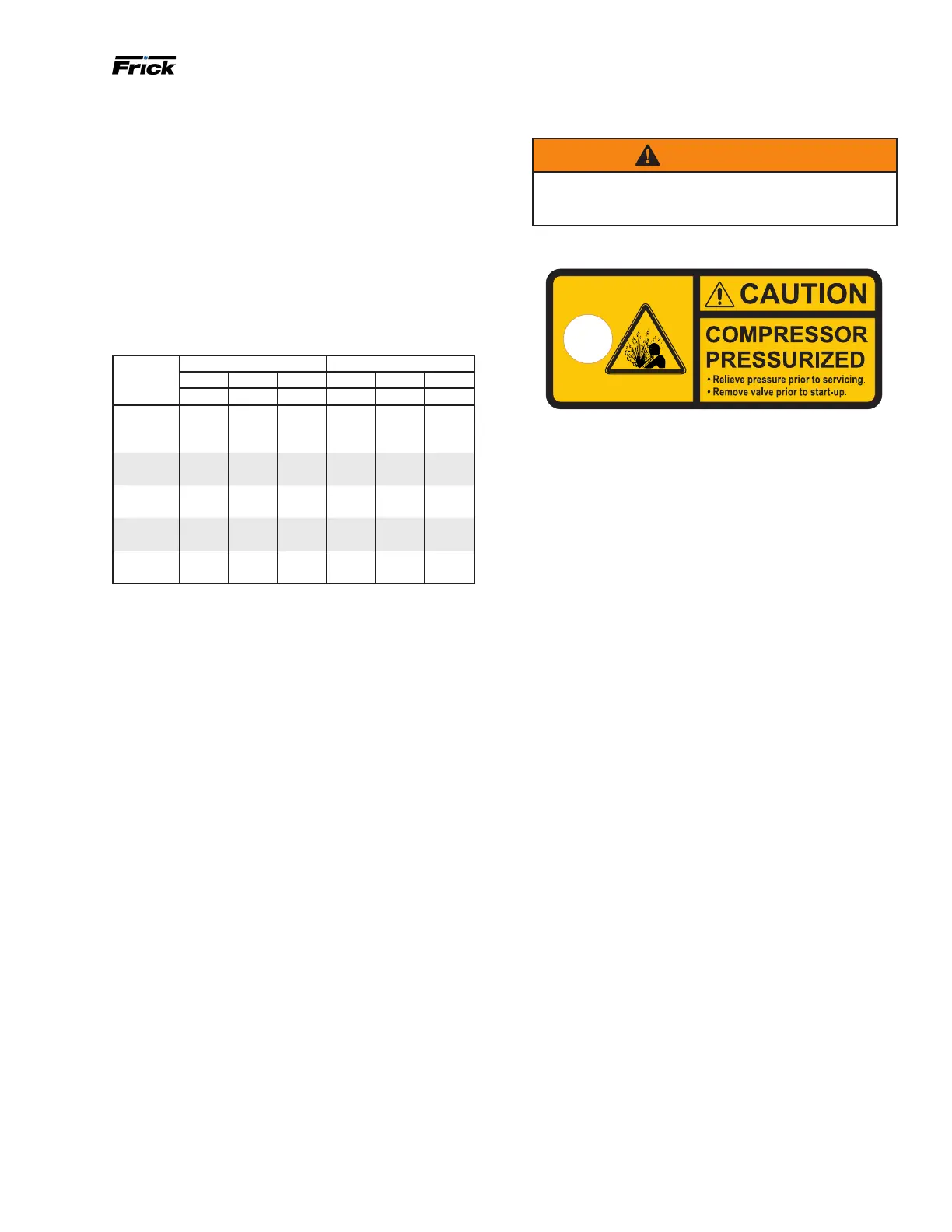
WARNING
Access valves in brass material must be removed and
the holes lled with steel plugs when package is as-
sembled.
Figure 9: Caution/identication tag on access valve
The oil system must provide oil to the compressor within
limitation on:
• Oil selection
• Oil pressure
• Oil temperature
• Oil cleanliness
Oil selection
The selected oil most be suitable for the application,
refrigerant and operation condition. The compressor
bearing require a minimum viscosity based on size and
speed, rpm. A maximum viscosity of 100 cSt should not be
exited. Frick compressor oils per 160.802-SPC are recom-
mended. Frick Coolware compressor selection program in-
clude properties for the Frick oils and provide information
on viscosity requirement for a given compressor selection.
Oil pressure
The complete oil system shall be designed for a pressure
dropnohigherthan15psiwithacleanoillterelement.
These is critical for the proper function of the balance
piston and ensure the life of the axial bearings. At booster,
low pressure and low pressure ratio operation an oil pump
mustbebuildintoprovidesufcientoilpressure.
The control system should have means to check the oil
pressure and compare to both suction and discharge pres-
sure. In general oil pressure shall be minimum (1.5 times
the suction pressure +15 psi) and higher than (discharge
pressure – 25 psi). For application with economizer and/or
sideload the oil pressure shall additional be more than 15
psi above the pressure at the side port when in operation.
Advanced control systems like the Frick Quantum will
check on the oil pressure in many more ways in order to
keep the compressor running beyond these basic lim-
its e.g. keep compressor running safely in partial loaded
condition.
Oil cooling requirements
Compressor oil needs to be cooled to control the discharge
temperature, maintain proper oil viscosity and to preserve
the life of the oil. Normally the discharge temperature will
be in the 170° to 180°F range (see CoolWare
™
).
 Loading...