070.250-IOM1 (NOV 2013)
Page 15
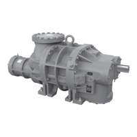
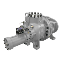
TDS_ Rotary Screw Compressor
Installation
Maximum radial runout is .004 in. total indicator reading.
Maximum axial runout is .004 in. total indicator reading.
A dial indicator or another appropriate measuring device is
to be used to determine the Total Indicator Runout.
Indicator bracket sag must be checked as all brackets have
someexibility.Thebestwaytomeasurethisistoattach
the dial indicator and bracket on a pipe at the coupling span
distance. Zero the indicator in the 12:00 position, and rotate
the pipe so the indicator is in the 6:00 position. The reading
on the indicator in the 6:00 position is the bracket sag. This
value must be included in the dial indicator readings when
afxedtothecouplingforanaccuratealignment.
Coupling alignment procedure
The life of the compressor shaft seal and bearings, as
well as the life of the motor bearings, is dependent upon
proper coupling alignment. Couplings may be aligned at
the factory but realignment must always be done on the
job site after the unit is securely mounted on its founda-
tion. Initial alignment must be made prior to start-up and
recheckedafterafewhoursofoperation.Final(HOT)eld
alignment can only be made when the unit is at operating
temperature.Afternal(HOT)alignmenthasbeenmade
and found to be satisfac tory for approximately one week,
the motor may be dowelled to maintain align ment.
NOTICE
Frick recommends cold aligning the motor .005” high.
This cold misalignment compensates for thermal growth
when the unit is at operating temperature.
Hot alignment of compressor/motor
Hot alignments can only be made after the unit has oper-
ated for several hours and all components are at operating
temperatures.
Shutdowntheunitandquicklyafxdialindicatortocou-
pling motor hub, then take readings of both the face and
rim of the compressor hub. If these readings are within
tolerance, record reading, attach coupling guard and
restart unit. However, if the reading is not within limits,
compare the hot reading with the cold alignment and ad-
just for this difference; i.e. if the rim at 0° and 180° read-
ings indicates that the motor rises 0.005 in. between its
hot and cold state, 0.005 in. of shims should be removed
from under the motor.
After the initial hot alignment adjustment is made, restart
unit and bring to operating temperature. Shut down and
recheck hot alignment. Repeat procedure unit hot align-
mentiswithinspeciedtolerance.
CAUTION
Install coupling guard before operating compressor.
SV position potentiometer
replacement and adjust ment
The Slide Valve Position potentiometer is located on the
end of the compressor unloader cylinder. See Figure 10.
Figure 10: Potentiometer
POTENTIOMETER
FLEXIBLE
COUPLING
COVER
LO CKNUT
1. Shut off control power.
2. Remove the four socket head cap screws securing the
potentiometer cover to the unloader cylinder.
3. Unsolder leads to the potentiometer and remove.
4. Loosen the setscrew on the potentiometer side of the
exiblecoupling.
5. Remove the locknut to remove the potentiometer
from the base plate. The potentiometer should slip out
of the coupling. For early versions, three retainer clips
that secure the poten tiometer to the base plate will need
removed.
6. Install the new potentiometer and reassemble.
7. Adjustment:
Rough adjustment is made with the slide valve fully un-
loaded and the control power off. Remove connector P5.
With a digital voltmeter, measure the resistance across the
red and white wires, having removed them from the SBC.
The resistance should be 1000 +/- 50 ohms. If adjustment
is necessary, loosen the locknut and rotate the potenti-
ometer clockwise or counterclock wise until the resistance
reading is a close to a 1000 ohms as possible. Retighten
the locknut and replace wires.
NOTICE
Mechanical travel of the slide valve potentio meter is 300
degrees rotation when the slide stop is conrmed to be
in the 2.2 Vi position. The travel will be less than 300
degrees if the slide stop is in any position above 2.2 Vi.
Fine adjustment must be made with the slide valve fully
unloaded and the compressor running. The Operating
display at this time should indicate a slide valve position of
0%. If the display is greater than 0%, adjust potentio meter
 Loading...