070.250-IOM1 (NOV 2013)
Page 12
TDS_ Rotary Screw Compressor
Installation
Holding charge and storage
Every TDS_ compressor is pressure and leak tested at the
Johnson Controls–Frick factory and then thoroughly evacu-
ated and charged with dry nitrogen to ensure its integrity
during shipping and short term storage prior to installation.
All compressors must be kept in a clean, dry location
to prevent corrosion damage. Compressors that will be
stored for more than two months must have their nitro-
gen charge checked periodically (see pages in GENERAL
INFORMATION for complete instructions).
WARNING
Holding-charge shipping gauges (if mounted) are rated
for 30 psig and are for checking the shipping charge
only. They must be removed before pressure testing
and operating the system. Failure to remove these
gauges may result in catastrophic failure of the gauge
resulting in serious injury or death.
Access valves are bronze and they must be replaced
with steel plugs when package is assembled.
CAUTION
This equipment has been pressurized with nitrogen
gas. Temporary valves and gauges have been
installed.
1. Relieve pressure before opening lines or making
eld connections.
2. Remove charging valves or gauges before pressur-
izing system.
3. Refer to installation operation and maintenance
manual for additional information.
Escaping gas may cause injury.
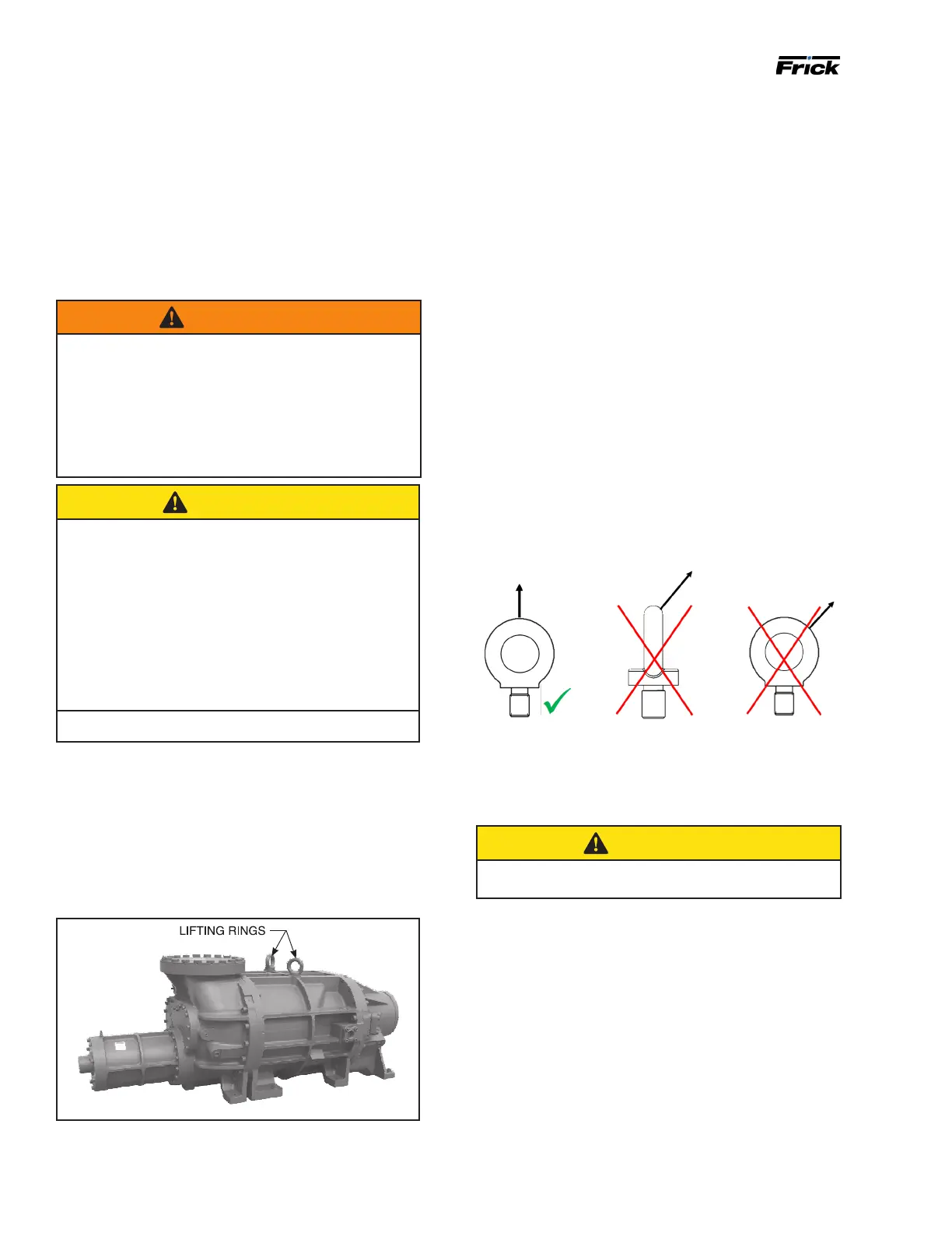
Rigging and handling
The compressor can be moved with rigging, using a crane
or forklift, by hooking into the two lifting rings on the main
housing (some models only have one ring). The compres-
sor lifting rings shall only be used to lift the compressor
itself.Seethefollowinggure.
Figure 7: Lifting rings, model 355
Lifting instructions
Lifting rings are located to facilitate the rigging and lifting
of the bare compressor. See Figure 8. Ensure only a quali-
edoperatorperformstheliftingandthattheyfollowthe
necessary precautions.
• Lift rings are intended for lifting the bare compressor
only.
• Examine the lift rings for damage before lifting the
compressor. Replace any damaged rings
• Fullyscrewintheliftringsandseatthemrmlyagainst
the contact surface before lifting.
• Load the lift rings in the vertical direction only; that
is, ensure the load is parallel to the threaded portion
of the lift ring. See Figure 8. This may require the use
of a spreader beam. Loading the lift rings at an angle
reduces their load capacity.
• Ensure that the load is level and stable before lifting
more than a few inches.
• Lift the compressor slowly.
• Remove the lift rings from the compressor before
operation. The vibration of a running compressor can
cause the lift rings to loosen and become damaged.
Figure 8: Lifting rings orientation
Foundation
Each
TDS_
Rotary Screw Compressor is shipped mounted
on a wooden skid, which must be removed prior to unit
installation.
CAUTION
Allow proper spacing for servicing (see Dimensional
Outline Drawing).
Therstrequirementofthecompressorfoundationisthat
it must be able to support the weight.
163S 1,220 lb 233S 2,670 lb
163L 1,280 lb 233L 2,950 lb
193S 1,720 lb 233XL 3,300 lb
193L 1,895 lb 283S 4,100 lb
355S 7,200 lb 355XL 9,200 lb
355L 8,240 lb 355U 10,200 lb
Screw compressors are capable of converting large quan-
tities of shaft power into gas compression in a relatively
small space. The compression process creates relatively
highfrequencyvibrationsthatrequiresufcientmassin
the base to effectively dampen them.
 Loading...