070.250-IOM1 (NOV 2013)
Page 16
TDS_ Rotary Screw Compressor
Installation
POT #4 on the SBC until 0% is indicated. If 0% is not at-
tainable, get as close as possible and then proceed to the
next step. The adjust ments of POT #4 and POT #3 are
interactive and POT #3 may require adjustment to allow
POT #4 to come into range.
Completely load the slide valve. The display at this time
should indicate 100%. If the display is less than 100%,
adjust potentiometer POT #3 on the SBC until 100% is
indicated.
Repeat this sequence until the slide valve indicates 0%
fully unloaded and 100% fully loaded.
Volumizer potentiometer
replacement and adjustment
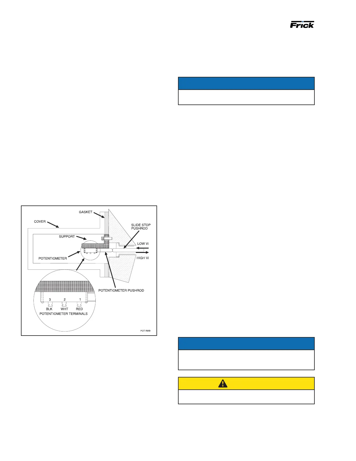
The volumizer potentiometer is located under a cover on
the right side of the compressor (facing shaft) at the inlet
end. See Figure 11.
1. Shut off control power.
2. Remove the potentiometer cover and gasket.
3. Remove the potentiometer and mounting bracket.
4. Install new potentiometer and bracket.
Figure 11: Potentiometer
5. Adjustment must be made with the compressor running
and the slide valve fully unloaded. With the slide stop
at maximum (Vi) position, check that the potentiometer
pushrod is in contact with the slide stop pushrod. If not,
the bracket must be ground or trimmed until contact is
made. Complete ly decrease the slide stop. The Operat-
ing display at this time should indicate a (Vi) of 2.2. If
greater than 2.2, adjust potentio meter POT #2 on the
SBC until 2.2 is indicated. If 2.2 is not ob tainable, get as
close as possible and proceed to the next step. Adjust-
ment of POT #2 and POT #1 are interac tive and POT #1
may require adjustment to allow POT #2 to come into
range. Now, completely increase the slide stop. The
display at this time should indicate a (Vi) of 5.0 (4.2 for
TDSH 283SX, 4.5 for TDSB 355U). If less than 5.0 (4.2 for
TDSH 283SX, 4.5 for TDSB 355U), adjust poten tiometer
POT #1 on the SBC until 5.0 (4.2 for TDSH 283SX, 4.5
for TDSB 355U) is indicated. Repeat this sequence until
the slide stop indicates 2.2 when fully decreased and
5.0 (4.2 for TDSH 283SX, 4.5 for TDSB 355U) when fully
increased.
NOTICE
The total travel on the volumizer
®
potentiometer is
.394 in.
Compressor hydraulic system
(The solenoid valves and manifold block are available as a
sales order option)
The compressor hydraulic system moves the movable
slide valve (MSV) to load and unload the compressor. It
also moves the movable slide stop (MSS) to increase or
decrease the compressor’s volume ratio (Vi).
The hydraulic cylinder located at the inlet end of the TDS
compressor serves a dual purpose. It is separated by a
xedbulkheadintotwosections.Themovableslidevalve
(MSV) sec tion is to the left of the bulkhead and the mov-
able slide stop (MSS) to the right. Both sections are con-
sidered double acting hydraulic cylinders as oil pressure
moves the pistons in either direction.
Both sections are controlled by double-acting, four-way
solenoid valves which are actuated when a signal from the
appropriate micropro cessor output energizes the solenoid
valve.
Compressor Loading: The compressor loads when MSV
solenoidYY2isenergizedandoilowsfromtheoil
manifold through valve ports P and B to cylinder port SC-2
and enters the load side of the cylinder. Simultaneously,
oilcontainedintheunloadsideofthecylinderowsout
cylinder port SC-1 through valve ports A and T to com-
pressor closed thread port.
Compressor Unloading: The compressor un loads when
MSVsolenoidYY1isenergizedandoilowsfromtheoil
manifold through valve ports P and A to cylinder port SC-1
and enters the unload side of the cylinder. Simultaneous-
ly,oilcontainedintheloadsideofthecylinderowsout
compressor port SC-2 through valve ports B and T to
com pressor closed thread port.
NOTICE
High Stage Operation: An alternative piping arrange-
ment has been provided to increase slide valve response
time during high stage operation.
CAUTION
Never open valve 1 and valve 2 at the same time during
compressor operation.
Higher operating pressures will slow the com pressor
unloading response time. Unloading response time can be
increased by closing valve 1 (oil manifold pressure) and
opening valve 2 to compressor suction pressure. See Figure
13.
 Loading...