070.250-IOM1 (NOV 2013)
Page 7
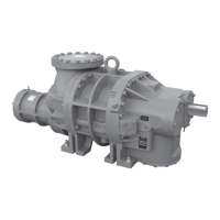
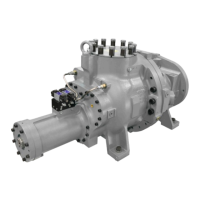
TDS_ Rotary Screw Compressor
Installation
Installation
Design limits
General information for all of the models is provided be-
low. Please see CoolWare to determine the limits for a
specic application.
TDS_ units are arranged for direct motor drive and require
aexibledrivecouplingtoconnectthecompressorto
the motor. The rotor and bearing design set limitations
must not be exceeded (See CoolWare). Refer to Johnson
Controls - Frick Compressor Control Panel instruction
090.022-O for additional information on setpoint limits.
Outline dimensions
Drawings for reference only can be found on the following
pages. Complete dimensions and access connections can
be found on the outline drawings.
TDSH 163 DWG# 534E0424
TDSH 193 DWG# 534E0425
TDSL 193 DWG# 534E0591
TDSH 233 1.35 & 1.7 DWG# 534D0224
TDSH 233 2.1 DWG# 534E0499
TDSL 233 DWG# 534D1025
TDSH 283 1.35 & 1.7 DWG# 534E0054
TDSH 283 2.1 DWG# 534E0605
TDSL 283 1.35 & 1.7 DWG# 534E0582
TDSL 283 2.4 DWG# 534E0583
TDXB 355 S, L, XL, U DWG# 534E1406
TDXH 355 S, L, XL, U DWG# 534E1406
If you do not have these drawings, please request any you
require by contacting Johnson Controls - Frick sales.
 Loading...