22
A
3
4
5
A
Fig. 2.7 a
1
2
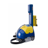
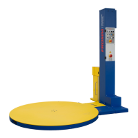
2.7 CARRELLI PORTA-BOBINA
Carrello versione FM / MB
Con questa versione di carrello è possibile regolare la
tensione di applicazione del lm sul bancale.
Il carrello
FM / MB
(Fig.2.7 a) è composto da un rullo gommato folle (1) e
da un rullo (2), munito di freno meccanico.
Agendo sulla manopola (3) si regola l’azione del freno
e di conseguenza la tensione del lm.
All’avviamento occorre caricare il lm sul carrello come
segue.
Portare il carrello in posizione bassa per facilitare
l'inserimento della bobina.
Premere il pulsante di emergenza per arrestare la
macchina.
Inserire la bobina (4) sulla spina di centraggio (5).
Inserire il lm tra i rulli secondo il percorso illustrato nello
schema A, il simbolo con i triangoli identica il lato del
lm su cui è applicato il collante (se presente).
Lo schema A è una targa adesiva presente anche sul
carrello.
Riarmare il pulsante di emergenza per ripristinare la
macchina.
2.7 ROLL-HOLDER CARRIAGES
FM / MB
roll-holder carriage
With this carriage version, the application tension of the
lm on the pallet can be adjusted.
The carriage FM/MB is composed of a rubber-coated
roller (1) and a roller (2) with mechanical brake.
The knob (3) is used to adjust the action of the brake
and, consequently, the tension of the lm.
Upon starting, the lm must be loaded onto the carriage
as follows.
Put the carriage into the Down position to make tting
the roll easier.
Press the emergency button to stop the machine.
Push the roll (4) onto the centre pin (5).
Insert the lm between the rollers following the path
indicated in gure A, the symbol with the triangles
identies the side of the lm to which the bonding agent
(if present) is applied.
Diagram A is an adhesive sticker also afxed to the
carriage.
Reset the emergency button to restart the machine.