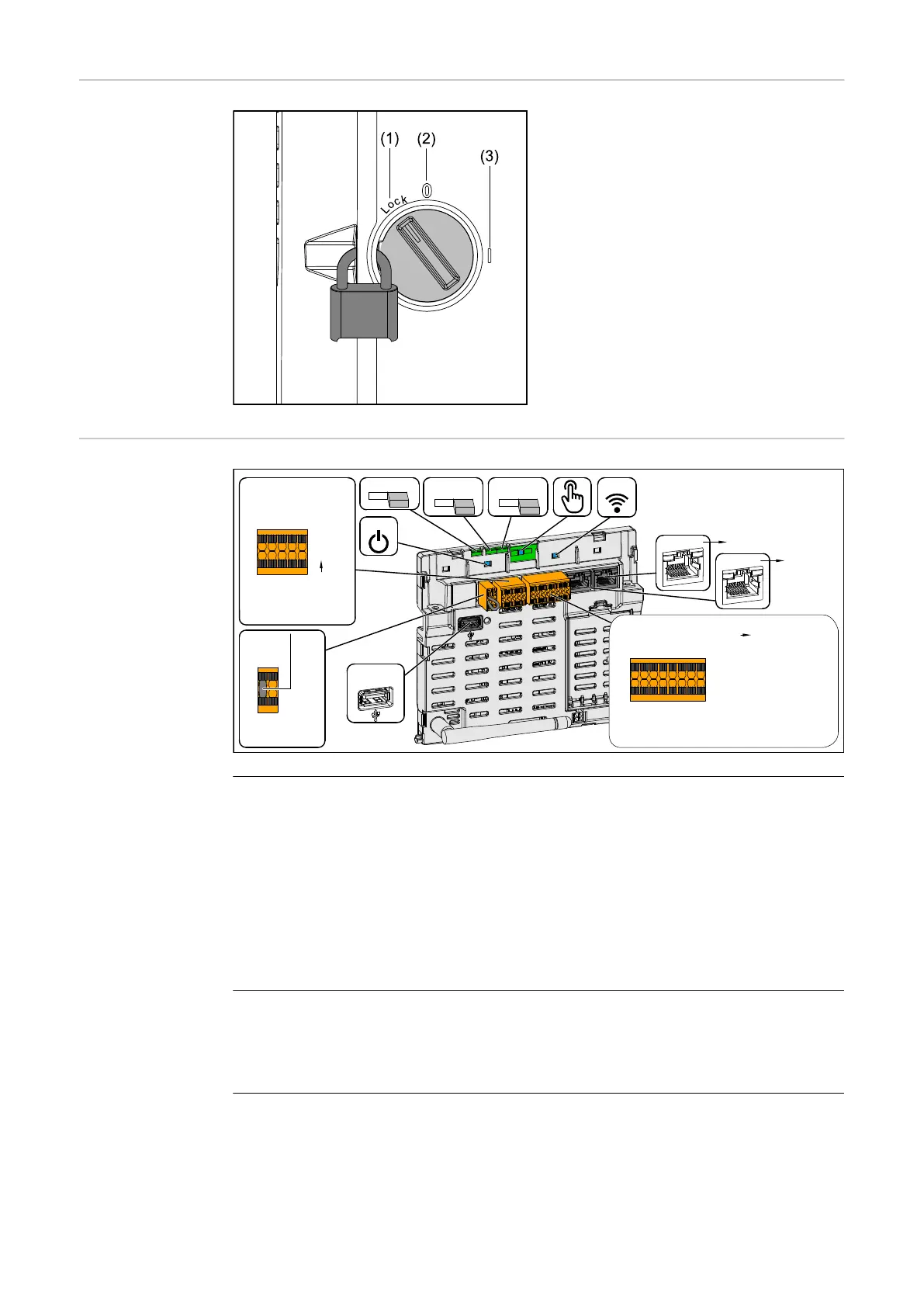
DC disconnector The DC disconnector has three switch set-
tings:
(1) Locked/off (turned to the left)
(2) Off
(3) On
IMPORTANT!
In switch settings (1) and (3), a conven-
tional padlock can be used to secure the
inverter against being switched on/off.
- The national guidelines must be com-
plied with in this respect.
Data communica-
tion area
WSD
10
Modbus
GND V+
M0- M0+
SHIELD SHIELD
M1- M1+
GND V+
RS485 (0/1) Fronius Smart Meter,
Ohmpilot, Battery (only GEN24),
Sunspec, Interface, ...
LAN 2
LAN 1
USB
(1A,5V)
Modbus 1
10
Modbus 0
10
Terminating resistor
LED
LED
WSD
IN+IN-
OUT+OUT-
WSD > wired disconnection
of grid feed-in
Factory default
Terminating resistor
Only inverter
to inverter
communication
IP: 169.254.0.180
IOs
GND
GND
V+
V+
IO1 IO0
IO3 IO2
IO5* IO4*
IN7* IN6*
IN9*
IN8*
IN11 IN10
Load Management,
Demand Respone Mode (DRM)*,
Back-up power, IO control, ...
IO4 = RG0 (Ref GEN/0)
IO5 = CL0 (COM LOAD/0)
IN6 = 1/5
IN7 = 2/6
IN8 = 3/7
IN9 = 4/8
I/Os
* Demand Response Mode (DRM)
Frequency band: channel 1-11(2412-2462 MHz)
Radio-frequency power: <100 mW (<20 dBm)
Technical Data (WLAN)
IP WLAN: 192.168.250.181 | Password: 12345678
Modbus terminal
Push-in terminal for the installation of
Modbus 0, Modbus 1, 12 V and GND
(ground).
The data connection to the connected
components is established via the Mod-
bus terminal. The inputs M0 and M1
can be selected for this purpose.
Max. 4 Modbus participants per input,
see chapter Modbus participants on
page 80.
WSD (wired shutdown) switch
Defines the inverter as a WSD master or
WSD slave.
Position 1: WSD master
Position 0: WSD slave
28

 Loading...


