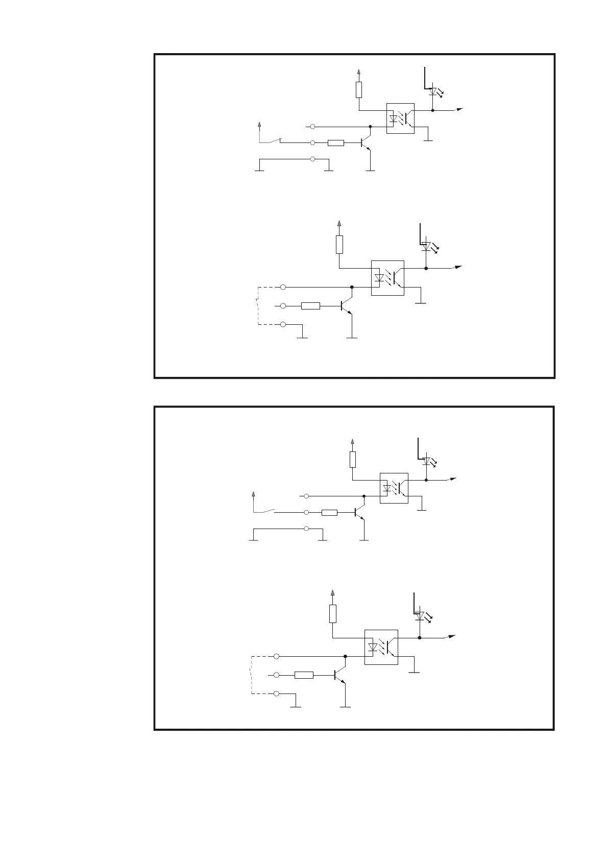
Version 1:
externe 24 V
Ansteuerung
Version 2:
Potentialfrei
(Klemme 1/3)
(Klemme 1/11)
+ 24 V von der
Automatensteuerung
V
DC
(intern)
max. 100 V
GND extern GND input GND input
GND uP
uP
V
DC
(intern)
(Klemme 1/10)
(Klemme 1/11)
max. 100 V
uP
GND uP
GND inputGND input
Klemme 1/3 ........ HI-Roboter ready / Quick-Stop
Klemme 1/11 ...... GND-Roboter ready / Quick-Stop
Klemme 1/10 ..... LO-Roboter ready / Quick-Stop
Klemme 1/11 ..... GND-Roboter ready / Quick-Stop
Automat
Stromquelle
(3)
(3)
Schweißbereitschaft der Stromquelle herstellen
Version 2:
Potentialfrei
(Klemme 1/4 bzw. 1/5)
(Klemme 2/13 bzw. 2/14)
+ 24 V von der
Automatensteuerung
V
DC
(intern)
max. 100 V
GND extern GND input GND input
GND uP
uP
V
DC
(intern)
(Klemme 1/12 bzw. 1/6)
(Klemme 2/13 bzw. 2/14)
max. 100 V
uP
GND uP
GND inputGND input
bzw.
Klemme 1/4 ....... HI-Job BIT 0
Klemme 1/5 ....... HI-Job BIT 1
Klemme 2/13 ..... GND-Job BIT 0
Klemme 2/14 ..... GND-Job BIT 1
Klemme 1/12 ..... LO-Job BIT 0
Klemme 1/6 ....... LO-Job BIT 1
Klemme 2/13 ..... GND-Job BIT 0
Klemme 2/14 ..... GND-Job BIT 1
Version 1:
externe 24 V
Ansteuerung
Automat
Stromquelle
(4) (5)
bzw.
(4) (5)
Bit 0 und 1 für Jobabruf setzen
6