85
EN-US
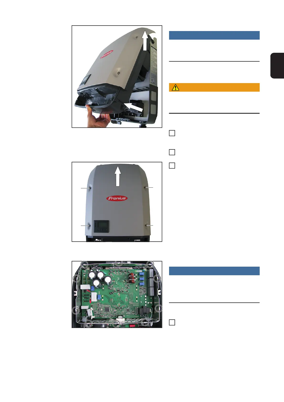
NOTE!
To avoid damage to the base shell, the
inverter must not exceed an angle of 11°.
WARNING!
Wait for the capacitors to discharge be-
fore continuing.
Lift the inverter from the Datcom area,
disconnecting the connection to the
wall bracket
Lift up and detach the inverter
Loosen the four 5x18 TX25 screws in-
cluding gaskets (4) and lift off the pow-
er stage set cover
Closing the Device:
NOTE!
To ensure a sufficient EMC connection
is established, all EMC springs must be
present
Check the correct position of the ten
EMC springs – the EMC springs are
held in place by small indentations
2
1
5
6
(4)
(4)
(4)
(4)
7
1
 Loading...


