iii
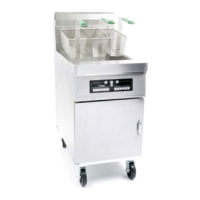
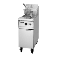
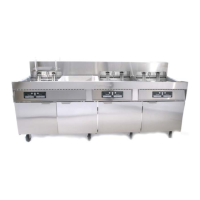
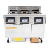
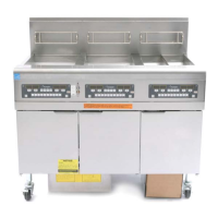
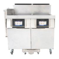
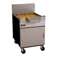
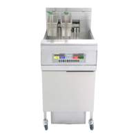
YFPRE SERIES ELECTRIC FRYERS
TABLE OF CONTENTS
CAUTIONARY STATEMENTS........................................................................................................ i
CHAPTER 1: Service Procedures
1.1 General .............................................................................................................................. 1-1
1.2 Replacing a Controller....................................................................................................... 1-1
1.3 Replacing Component Box Components ..........................................................................1-1
1.4 Replacing a High-Limit Thermostat.................................................................................. 1-2
1.5 Replacing a Temperature Probe ........................................................................................ 1-3
1.6 Replacing a Heating Element............................................................................................ 1-5
1.7 Replacing Contactor Box Components............................................................................. 1-6
1.8 Replacing a Frypot ............................................................................................................1-7
1.9 Built-In Filtration System Service Procedures.................................................................. 1-9
1.9.1 Filtration System Problem Resolution ............................................................... 1-9
1.9.2 Replacing the Filter Motor, Filter Pump and Related Components.................1-10
1.9.3 Replacing the Filter Transformer or Filter Relay............................................. 1-12
1.10 Interface Board Diagnostic Chart.................................................................................... 1-13
1.11 Probe Resistance Chart.................................................................................................... 1-14
1.12 Wiring Diagrams.............................................................................................................1-15
1.12.1 Standard Wiring YFPRE.................................................................................. 1-15
1.12.2 Tilt Switch Wiring............................................................................................ 1-16
1.12.3 Terminal Block Wiring .................................................................................... 1-16
1.12.4 Contactor Box - 3 Phase/Delta Configuration.................................................. 1-17
1.12.5 Contactor Box - Single Phase Configuration ................................................... 1-18
CHAPTER 2: Parts List
2.1 Accessories........................................................................................................................ 2-1
2.2 Cabinetry ........................................................................................................................... 2-2
2.3 Drain Valve ....................................................................................................................... 2-4
2.4 Electronics and Electrical Components............................................................................. 2-5
2.4.1 Element Assembly and Hardware...................................................................... 2-5
2.4.2 Tilt Switch Assembly.........................................................................................2-6
2.4.3 Controllers..........................................................................................................2-7
2.4.4 Contactor Boxes ................................................................................................. 2-8
2.4.5 Component Boxes ..............................................................................................2-9
2.5 Wiring ............................................................................................................................. 2-10
2.5.1 Contactor Box Wiring Assembly, 12-Pin (Control)......................................... 2-10
2.5.2 Contactor Box Wiring Assembly, MDI, 6-Pin (Left Element)........................ 2-10
2.5.3 Contactor Box Wiring Assembly, MDI, 9-Pin (Right Element)...................... 2-10
2.5.4 Component Box to Filter Pump Harness.......................................................... 2-11
2.5.5 Main Wiring Harnesses.................................................................................... 2-11
2.5.6 Component Box and Filter Pump..................................................................... 2-11
2.6 Filtration System Components........................................................................................ 2-12
2.7 Frypots and Associated Components .............................................................................. 2-14
2.8 Wiring and Pin Connectors ............................................................................................. 2-14
2.9 Fasteners.......................................................................................................................... 2-15