32
WWW.FUHR.DE
multitronic
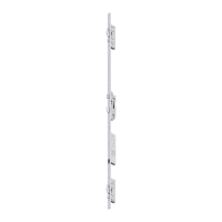
881/881GL/ServoAccess
4.2.7 INSTALLATION OF THE CONTROL UNIT HOUSUNG IN THE
DOOR FRAME
CLICK
click
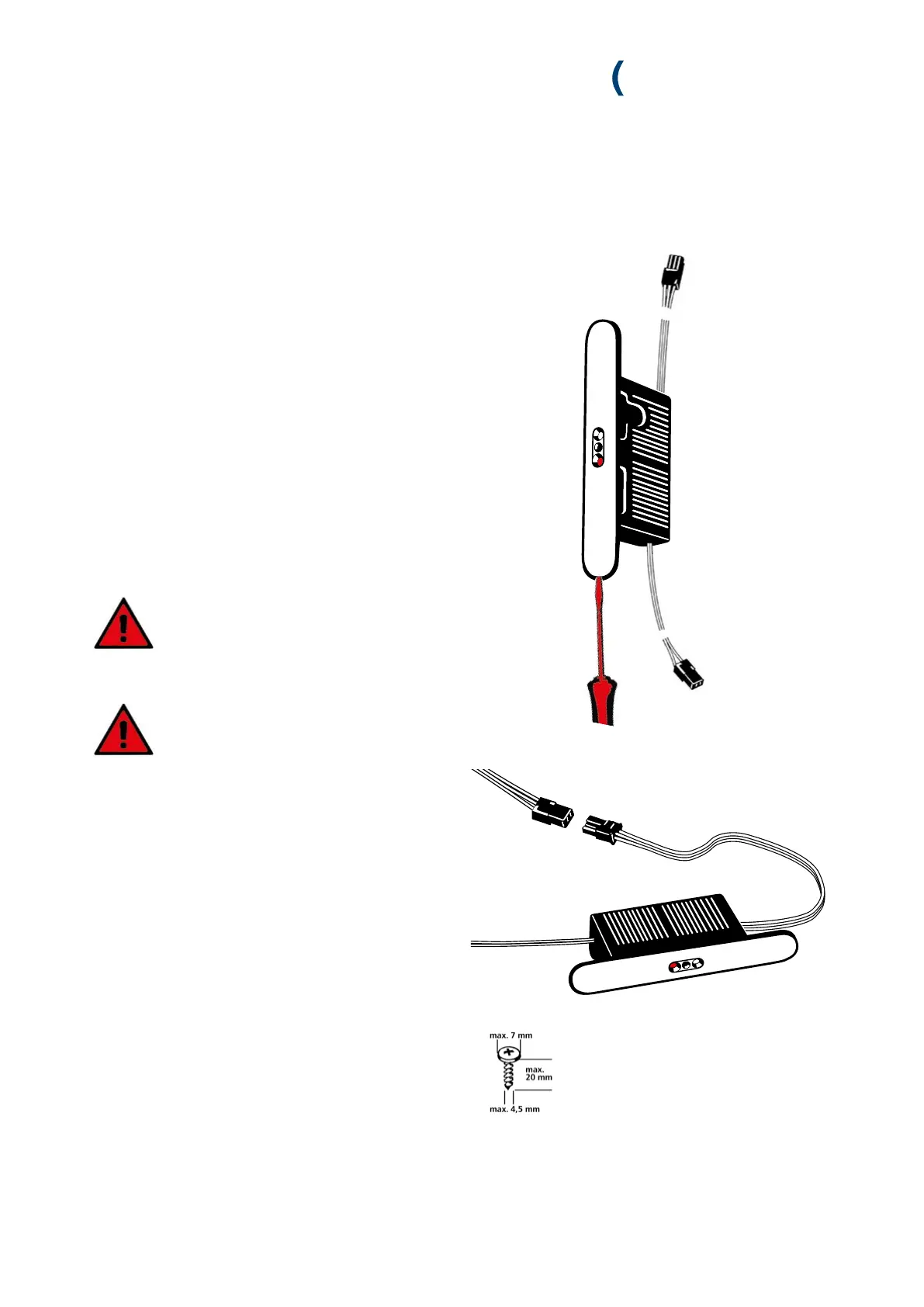
1. Remove the stainless steel cover before mounting the con-
trol unit housing. This is held by two magnets and can be
easily removed. To do this, carefully grasp the recess in
the cover plate with a small screwdriver or fingernail and
remove the cover plate.
2. Connect up the surface-contact device’s 3-core cable plug
(red, black, white) with the control unit casing’s 3-core
cable plug. The plug clicks in audibly.
3. Insert the 2-core control unit casing cable into the routed
recess, guide the cable downwards, and exit through the
switching power supply unit’s routed recess.
4. Carefully feed the control unit casing’s cable back into the
frame profile so that the control unit casing fits comfor-
tably in the routed recess.
Please ensure that the cables are neither
kinked, trapped nor damaged by sharp
profile edges.
5. Screw-fix the control unit casing into the frame profile.
Ensure that the cables are not damaged
when screw-fixing.
6. Replace the control unit casing’s cover cap.